Table of Contents
- Introduction
- Description of the Circuit Design
- Installation in the Enclosures
- Audiophile Review
- VV8 CM
Introduction
May 7, 2023
Since the release of the VV7 preamplifier, I have been repeatedly asked to develop a multi-channel preamplifier without a phono stage. The desired number of channels ranged from four to eight. In early 2023, I finally decided to build such an eight-channel preamplifier based on the OPA1632 linear stage from the VV7 project.
For this project as well, I relied on the proven technology from the XOno 2019 project. To this day, I see no reason to improve the relevant circuits (DC power supply), which is why they continue to perform very well in this preamplifier.
Description of the Circuit Design
May 7, 2023
The heart of the preamplifier is a circuit board with a total of four audio channels. The VV8 features two of these circuit boards. This allows the preamplifier to be used, for example, in stereo mode with four channels per stereo channel. This is ideal for an active speaker system with up to four channels.
Preamplifier Circuit
As I mentioned above, the OPA1632 forms the basis of the preamp. I’ve come to appreciate this balanced operational amplifier from Texas Instruments in various projects. Rumor has it that this op-amp has a supersymmetrical internal design — in any case, it sounds absolutely amazing.
The MUSES72320 digital potentiometer is located at the beginning of a channel’s signal path. It remains the best chip for this function. The MUSES is a dual-channel device, making it ideal for use in a balanced design. The potentiometer’s outputs must be loaded with a high-impedance load; otherwise, linear attenuation cannot be achieved (keyword: loaded voltage divider). I decided to use a discrete buffer amplifier with 2SK2145 JFETs.
The circuit featuring the OPA1632 is connected to the buffers. Since it can be designed with low impedance, the op-amp’s excellent inherent noise performance is not compromised. Integrated high-current buffers are connected to the two outputs of the balanced operational amplifier. These are included in the feedback loop of the OPA1632. Thanks to these drivers, even larger line capacitances do not cause any problems. Their integration into the feedback loop also guarantees the neutrality of these drivers.
A servo controller is used as the final stage of a linear amplifier. This ensures that the outputs are free of DC voltage components. As a result, the linear amplifier can be operated without an output coupling capacitor.
Each circuit board features a symmetrical voltage regulator based on my preferred modified topology by Walt Jung. However, I had to adapt the modified Jung regulator to the lower operating voltage. The board also includes a digital control circuit that is electrically isolated from the controller.
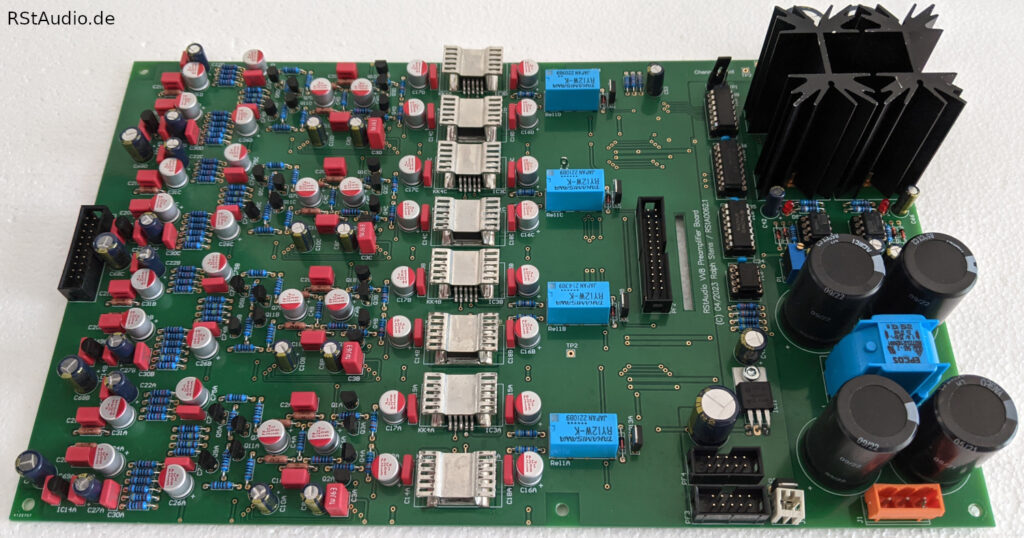
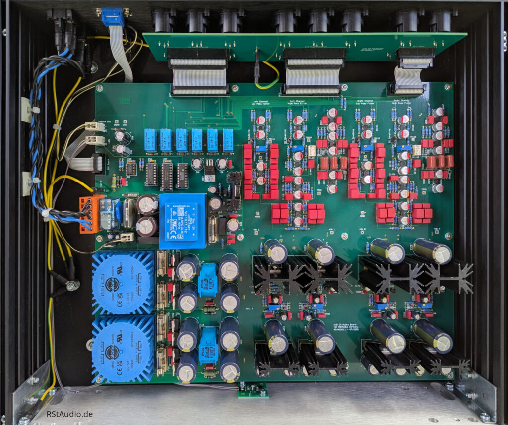
The photo above shows the audio circuit board from above. The preamplifier stages are located on the left side. The digital control circuitry is mounted in a narrow strip on the circuit board to the right of them. The power supply can be seen on the far right.
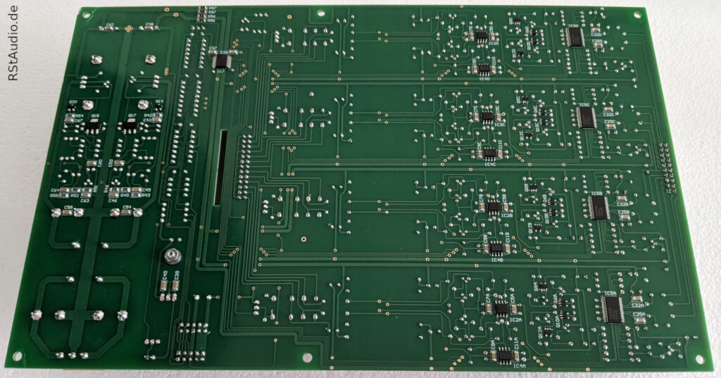
As you can see in the photo above, many of the components on the VV8 are SMDs. I placed most of them on the bottom side of the board. This usually results in a simpler layout for a 2-layer board.
Each audio circuit board is connected to a backplane equipped with the necessary XLR connectors. The circuit board is connected to the linear amplifiers via two ribbon cables.
Power Supply
You can read about the power supply design in some of my projects, such as XOno 2019, VV5.4, and VV7. The VV8 also utilizes the proven configuration consisting of a Schurter power jack, a 230V/AC DC filter, toroidal transformers from Müller Elektrotechnik, and printed circuit boards for an unregulated power supply.
In my opinion, this design for generating unregulated symmetrical DC voltages for analog circuits remains state-of-the-art to this day. As far as I’m concerned, no changes are necessary.
Control
At the heart of the controller is once again the AT89C51ED2 microcontroller from Microchip, which I prefer to use here. I also use it in all my other preamplifier projects.
An SPI bus and an I2C bus are used. As long as no switching operations are taking place, both serial data transmissions remain in a static state. This prevents interference in the analog circuits during normal operation. Even during switching operations, the electrical isolation between the digital and analog circuits ensures interference-free operation.
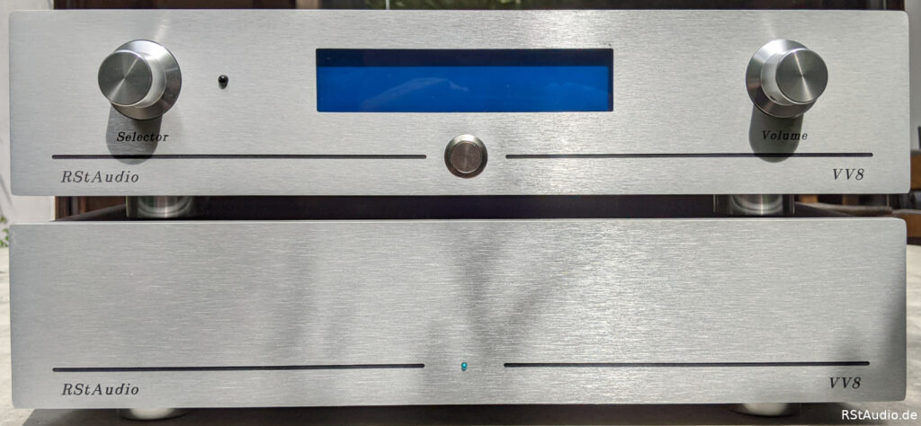
The preamplifier is operated via two rotary encoders with push buttons and a two-line, 20-column LCD display. There is also a remote control that emulates the function of the rotary encoders. The front panel also features a push button used to turn the preamplifier on and off.
Installation in the Enclosures
May 26, 2023
The amount of material required is so substantial that two enclosures are needed per preamplifier, which is nothing new in my designs. When laying out the electronics, I based my approach on the VV5.4 preamplifier. Of course, I once again used the proven enclosures from Italy.
Control Unit
The 230V/AC power supply, the generation of unregulated DC voltages, and the microcontroller system are housed in the control unit.
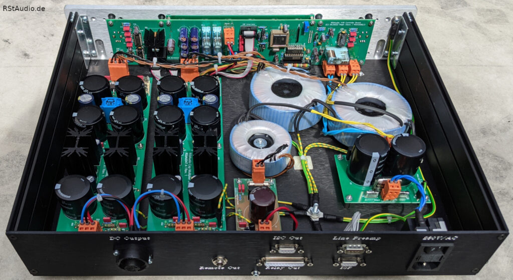
The photo above shows the assembly. Behind the front panel, the circuit board containing the microcontroller system is bolted in place. On the right side of the photo, you can see the circuit board with the 230V/AC DC filter. Behind it are the two toroidal transformers that supply power to the audio circuits. The third, smaller transformer is intended for the digital circuitry.
In the center front is the small circuit board containing the unregulated power supply for the digital circuits. To the left of it are the two unregulated power supplies for the analog power supplies.
Audio Unit
The audio unit houses the two audio circuit boards, including the associated backplanes.
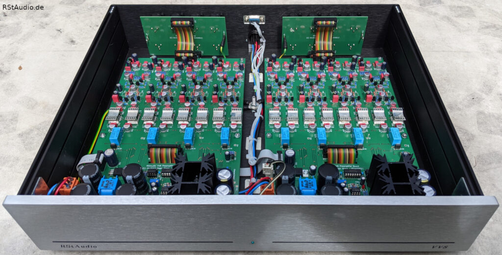
As you can see in the photo above, the Audio Unit’s enclosure is also quite full, containing the two audio PCBs and their associated backplanes.
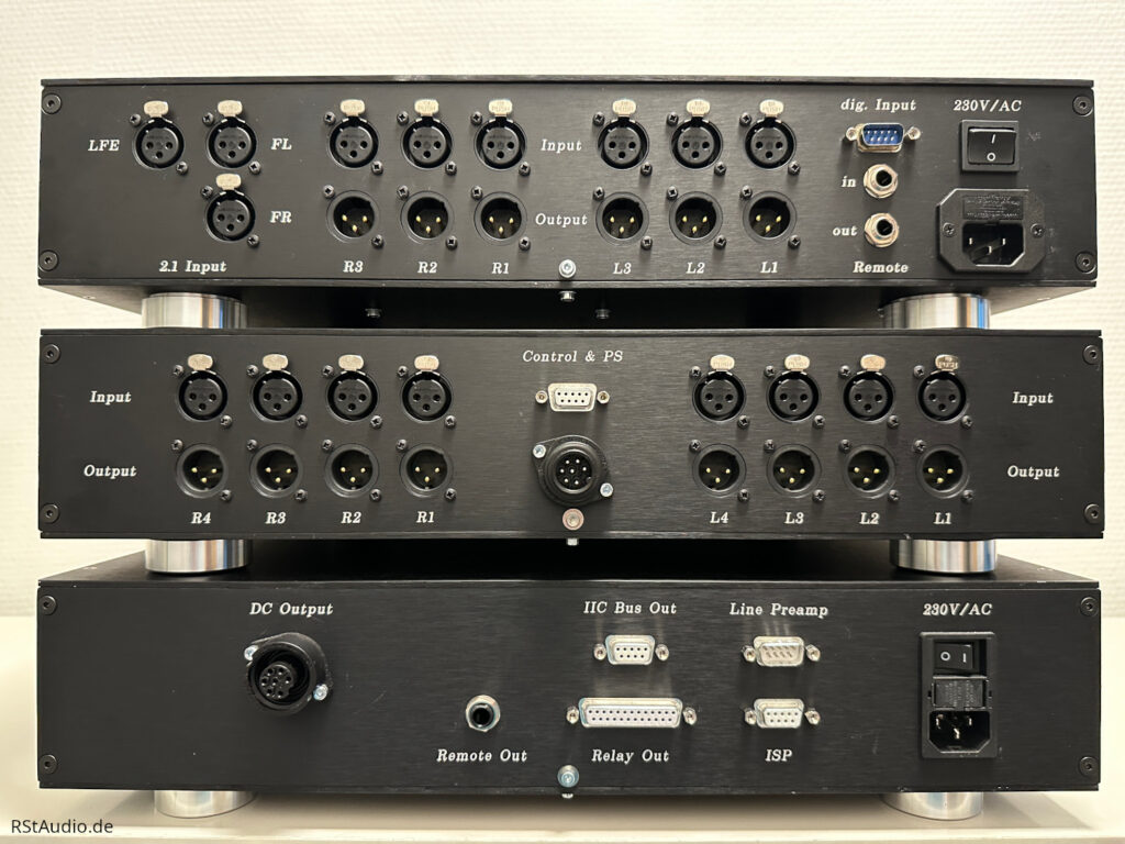
Connections
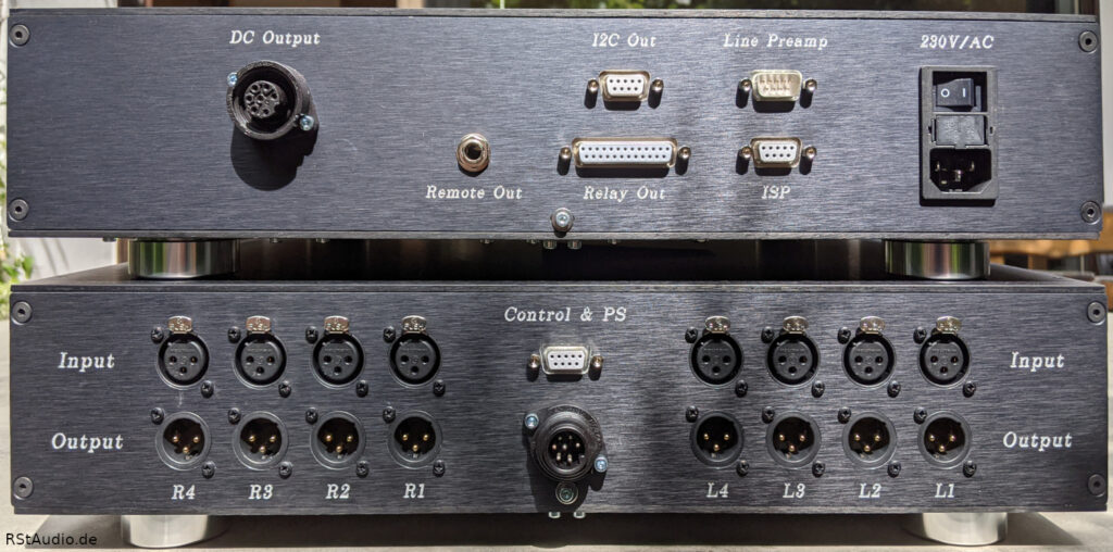
If you look at the back of the VV8, you’ll naturally see the preamp’s connectors. In the photo above, the Control Unit is mounted on top of the Audio Unit. You can easily tell this by the type of connectors.
On the right side of the Control Unit is the power connector with a switch, fuses, and a power filter from Schurter. To the left of this, the connection cable for the control link between the Control Unit and the Audio Unit is plugged into the port labeled “Line Preamp”. This is a standard 9-pin Sub-D cable. The microcontroller can be updated with new embedded software via the port labeled “ISP”.
In the center of the rear panel are Sub-D connectors for expansion. The “I2C Out” connector carries an isolated I2C bus. There is currently no application for this. The connector labeled “Relay Out” can be used to connect an audio switch with five balanced inputs.
The “Remote Out” jack carries a control voltage that can be used to turn other components in the system on and off.
The jack on the far left of the back of the control unit provides an additional connection to the audio unit. This jack supplies power to the audio circuitry. A 7-pin cable is used, which I configure myself.
In the center of the Audio Unit, you can see the corresponding connectors for the two connections to the Control Unit. These jacks are labeled “Control & PS.” At the top is the Sub-D cable for control, and at the bottom is the cable for powering the audio circuits.
To the left and right of these are the XLR connectors for the audio signals. The inputs are at the top and the corresponding outputs at the bottom. There are two groups assigned to the two audio circuit boards. Accordingly, the individual inputs and outputs are labeled L1 … L4 and R1 … R4, respectively. When viewed from the front, the audio connectors are also correctly arranged.
Audiophile Review
November 14, 2023
Since I’m already very familiar with the circuitry in my VV7 preamplifier, there were no surprises. The VV8 performs at the high level I expected. It is a very successful design, created for a high-end system with a topology similar to my RQM speaker system — that is, an active multi-way system with digital crossovers.
Ralph Stens
I’ve had the VV8 for a few weeks now. My previous preamp, which was connected to a Lynx Aurora, was a 6-channel, unbalanced model. But I wanted to try out a 4-way/8-channel setup.
So, eight channels, balanced, each channel independent yet controllable as a whole, and a balance control—that was on my wish list. I’d had the chance to listen to the VV6 at Heiner F.’s place, so I reached out to Ralph. As it happened, he was already planning the VV8. To be honest, I didn’t have high expectations for the preamp’s sound—it already sounded very good.
Now, after a few weeks, I can say that the VV8 has completely transformed my system. No matter what I focus on — spatiality, timbre, airiness, depth, or sense of scale — everything sounds a little more beautiful and authentic. The VV8 has far exceeded my expectations. It’s a fantastic 8-channel preamplifier.
My Stereo System:
Karl S.
- Lenco with Mørch DP8 and Ortofon Windfeld
- RStAudio XOno and D3a Phono
- Lynx Aurora, Acourate, VV8
- Power Amplifiers (all DIY):
Bass Pass F5, Mid Vt52, Mid-high 300B, High AD1- Speaker:
Large bass horn, Sato horn with a driver by D. Hampel, JBL2344 with TAD2001, Fostex T825
I have always chosen my audio equipment carefully, with a view to ensuring a long service life.
I’ve been using Ralph’s design and the resulting VV8 preamp here for weeks now, and I’d like to write a few lines about it.
If you dare to unscrew the covers, you won’t see a mess, but rather electronics that are extremely clean and well-organized in every respect.
This preamplifier is designed for up to 8 channels. It is ideal for an active system with up to 2 sets of 4 drivers. To be able to compare it with other preamplifiers, I tested this preamplifier with two power amplifiers and passive speakers.
There are sound descriptions ranging from digital coldness to the warmth of tube amplifiers.
If you prefer one extreme or the other, the VV8 isn’t for you, because the VV8 simply doesn’t have a sound signature. In my view, that’s the highest praise you can give an audio device. It’s simply wonderful when there’s no sound signature and the music stands on its own.
The features described for 2-channel operation are not compromised in 6- or 8-channel operation. Simply wonderful!
Uli J.
VV8 CM
September 14, 2025
In early 2025, Carousel asked me to design an expansion module for his VV8. The hardware was to include a multiplexer and an active 2-way crossover, allowing him to switch between his 9.2.6 system and stereo playback.
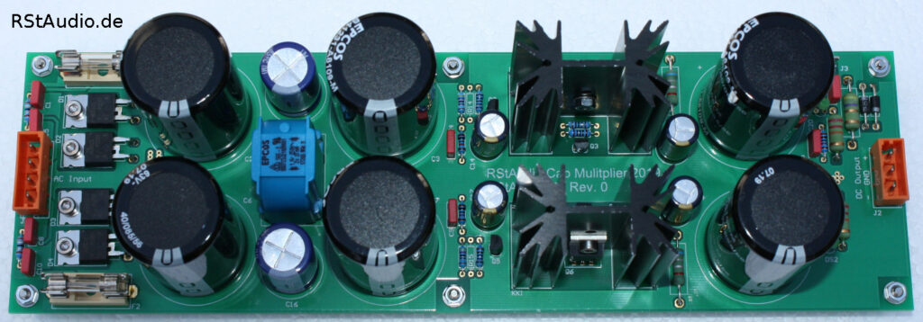
I decided to put everything on a single board. However, I didn’t want to compromise on proven technology. For the active filters, I’m using dual-mono power supplies with capacitance multipliers and Jung regulators. The filters themselves are 4th-order Linkwitz-Riley filters implemented using a Sallen-Key topology. The frequency-determining components (R and C) in the crossovers are all calibrated with an accuracy of ±0.25%. In addition, I placed great emphasis on achieving the best possible signal-to-noise ratio (less than -100dB in the filter’s stopband).
I gave the system the additional designation CM, standing for “Crossover Multiplexer.”
When the device was delivered, I asked Carousel for a description of its system:
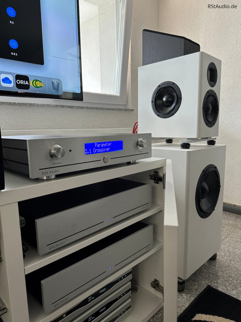
I have two sound systems in my listening room. There is a stereo system with three-way active crossover speakers. And there is a 9.1.6 surround sound system, for which the .1. LFE signal is sent to two 10-inch subs. So it could be called a 9.2.6 system.
There are two preamplifiers for these two systems. There is an eight-channel RStAudio VV8 preamplifier, with which I only use six-channels for my two three-way active crossover speakers for stereo. And there is an SPL MC16 for sixteen channels of surround sound.
The challenge here was that, when playing surround sound, the front left and right channels were sent only to the 6.5-inch midrange drivers. These are very capable drivers with very flat response from 100 Hz to 5000 Hz. But I was missing out on high-end for surround sound.
Therefore, I asked RStAudio to build a crossover multiplexer. When playing stereo, the VV8 CM would pass through six channels (stereo three-way) with no loss in quality to the main VV8 preamplifier. And when playing surround sound, the VV8 CM would take three-channel 2.1 input from the SPL MC16 preamplifier… that is, front left, front right and LFE subwoofer feeds… and split the LFE subwoofer channel for the two 10-inch subs… while also splitting the front left and right channels at 2500 Hz to feed the mids and the tweeters separately.
As an added complication here, when in 2.1 mode, the VV8 should pass through the signal from the MC16 at 0 dB. But, to avoid blowing the tweeters at any point by feeding them a line-level signal by accident, whenever the VV8 would be switched between modes, it should be placed in mute automatically. And if not in pass through mode, then it should default to a given selectable setting, -50 dB in my case… as well as to be in mute.
RStAudio did a wonderful job of this. As an additional “surprise and delight”, which was not in the original specification, the option to use a time-delay was built into the high-pass filter to adjust for the fact that my tweeters and midranges are mounted in the same vertical plane. This can be turned off or turned on.
Many thanks to RStAudio!
Carousel, September 2025
You can also find some information about the system on the Audio Science Review Forum.