Table of Contents
- Introduction
- Selection of Semiconductors
- Power Supply for the Analog Electronics
- Preamplifier
- Initial Commissioning of the Audio Electronics
- Volume & Gain Settings
- Input Selection Switch
- Microcontroller Board
- I²C Bus Relay Driver Board
- Power Supply for the Relays
- Software Description
- Commissioning of all Components
- Enclosure
- Wiring the Preamplifier
- Updates & Improvements
Introduction
February 23, 2006
Shortly after I decided to build myself an Aleph JX power amplifier (which I never actually did), I became convinced that I should convert my entire amplifier chain to the Aleph philosophy. So, at the same time as working on the power amplifier, I also started thinking about the preamplifier. By the way, this is my third DIY preamp, hence the name VV III (Preamp 3). I know, it’s not very original. I chose the Aleph P in version 1.7 and prioritized this project so that I could finish the preamp first, as the central element of the audio chain.
With the exception of the dual-mono design — of which I am a strong advocate — I carried over the amplifier circuitry, including the power supply, from the original. When building audio components yourself, you’re not bound by commercial considerations and can give free rein to your imagination and vision. The control system is largely based on my own ideas and, in particular, on my hardware and software. However, if you fully exploit the possibilities offered by the existing hardware, you will quickly encounter parallels in the operation of other projects. The distribution of the overall electronics across so many circuit boards is intentional and has the advantage that individual parts (e.g., volume control via relays) can be easily modified without having to redesign the entire preamplifier.
A wealth of information on Nelson Pass’s audio circuits can be found on PassDIY.com and diyAudio.com.
Selection of Semiconductors
February 23, 2006
Because of the need for symmetry in the two amplifier stages of the differential amplifier, the MOSFETs must have electrical characteristics that are as identical as possible. I purchased 50 units each of the IRF610 and IRF9610 types from a single batch at Conrad. Semiconductors from a single batch usually come from the same wafer and therefore have very similar physical properties.
I used Nelson Pass’s article “How To: Matching Devices” as a guide for the selection. The corresponding measurement circuits can be viewed here.
A 12V/7Ah battery was used as the voltage source. This ensured that no control signal from a power supply was present in the DC voltage. The battery voltage was continuously monitored during the measurement. A high-precision Agilent 34401A benchtop multimeter with maximum resolution (6 decimal places – 100μV) was used to measure the gate-source voltage.
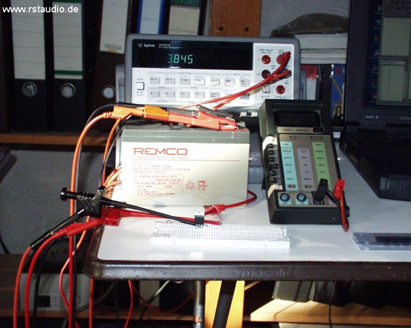
Since temperature has a significant impact on the results, the transistors were left in the measurement circuit until a stable state was reached (up to five minutes, until the MOSFETs were lukewarm). In addition, the transistor was covered during the measurement to minimize any influence from drafts. Transistors with a deviation of no more than 1mV were flagged as potential candidates and subsequently measured differentially.
For this measurement, the test circuit was set up twice; the two transistors were thermally isolated from each other, and then the voltage between the two gates (IRF610) and the two sources (IRF9610) was measured (see the corresponding test circuits).
I reserved the two pairs with the smallest deviations in the IRF610 for the actual amplifiers. The next two in the series were used for the lower current sources (toward ground). Accordingly, the two pairs with the smallest differential deviations in the IRF9610 were used in the upper current sources. The result of this selection will become apparent after the preamplifiers are assembled, based on the differential voltages between the outputs of a channel.
Power Supply for the Analog Electronics
February 25, 2006
The analog power supply was taken from the original. Unlike the Aleph P, however, it was built as a dual-mono version: Both channels have their own transformer (toroidal, 2x 30V/50VA) and their own regulation. This involves stabilization using a source follower (there are plenty of suitable transistors available, see above) and a reference voltage generated by Zener diodes. Strictly speaking, this is not a regulation circuit, as there is no feedback. At the output, there is an electrolytic capacitor that forms a CRC filter with the operating voltage input of the actual preamplifier (1000μF – 3.3Ω – 2x 1000μF).
- Schematic Diagram of the analog power supply
- Board Assembly
Here is the fully assembled board (Rev. 1):
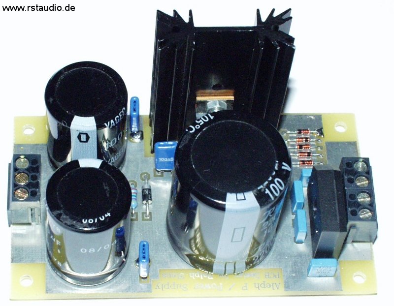
The actual circuit remained unchanged in Revision 1; only the layout of some components was adjusted. However, a 4-way terminal block with two directly connected terminals was added to the input for connecting the two secondary windings of the toroidal transformer (2x 30V) in series. The terminal block at the output was also expanded by one connection. This third connection is grounded and serves to enable a connection to ground via two diodes connected in anti-parallel (bridge rectifier) (see below).
Preamplifier
February 25, 2006
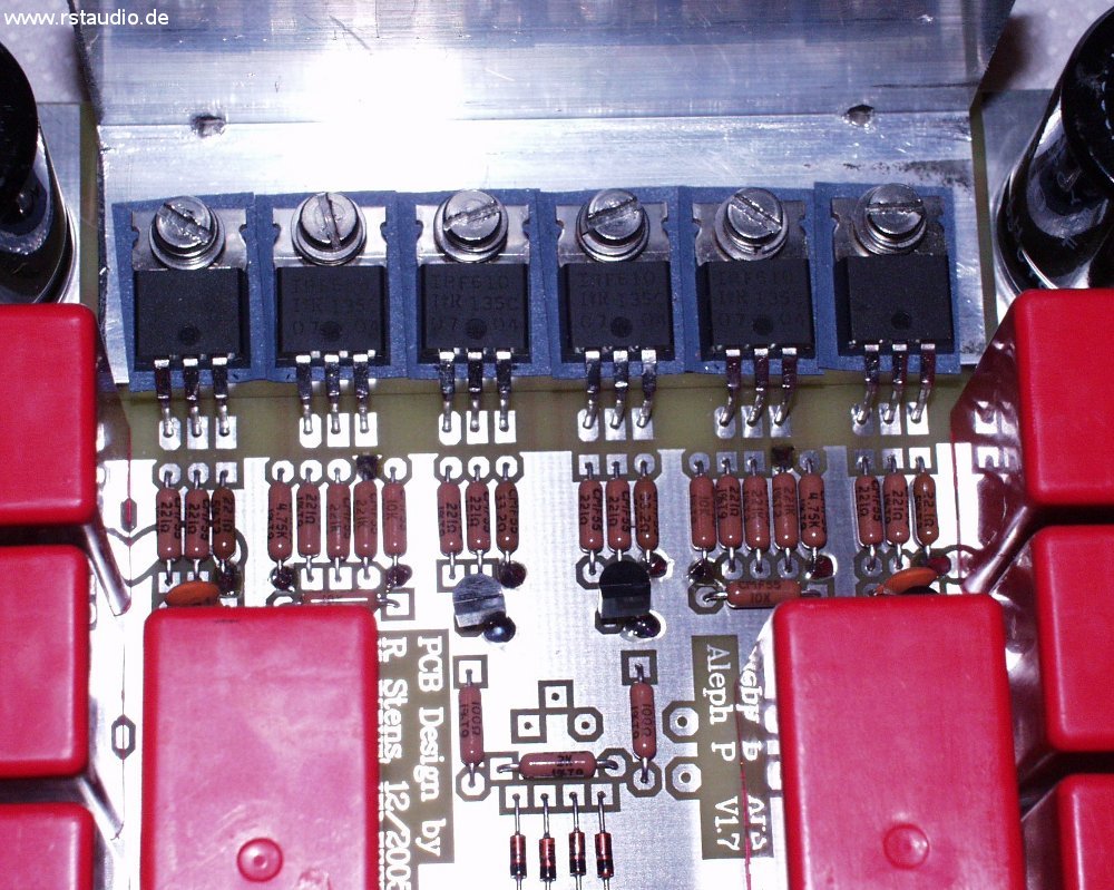
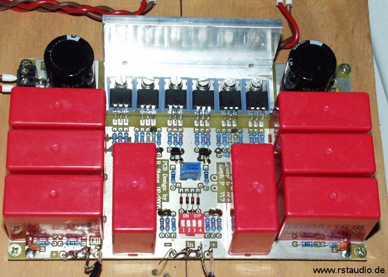
As the title suggests, the actual preamplifier is an Aleph P version 1.7, which means the current sources are implemented using active components (MOSFETs) (in the first version, resistors were used in this section). The two complementary types IRF610 and IRF9610 from International Rectifier are used as active elements. Unlike the original circuit, I have used the BC550C/BC560C types, which are more readily available in Europe, instead of the ZTX450/ZTX550 bipolar transistors. The amplifier consists of two identical sections, each responsible for one half of the differential input signal. These signals are coupled at the respective gate and tapped at the drain. Thus, each half of the amplifier rotates the phase by 180°. Consequently, the negative output signal is tapped from the positive input stage of the amplifier, and vice versa.
Both amplifier stages are coupled via resistors R51, R66, PGain, and PG. This is where the circuit’s internal gain is set. The two gain controls for the left and right channels of the original design also function here. On the board presented here, a potentiometer (PGain) can be installed at this point. Alternatively, desired resistors can also be switched by the microcontroller on an external board (in this case, the switchable resistors are connected to J5a and J5b, respectively). This method of operation is intended for the final configuration. The potentiometer is used for initial setup and testing on the lab bench and will no longer be present in the final installation.
As in the original, resistors can be enabled or disabled at the input using a 4-position DIP switch. This allows the input signal attenuation to be preset, enabling the preamplifier’s overall gain to be adjusted to the user’s individual needs.
The amplifier’s AC coupling is achieved using Wima MKP4 capacitors rated at 10μF/160V. The eight capacitors required take up most of the circuit board. All six MOSFETs are mounted on an L-shaped heat sink. This ensures thermal equilibrium among all the transistors. If necessary, a heat sink can also be easily mounted on the L-shaped bracket.
- Schematic Diagram of the Aleph P Preamplifier
- Board Assembly
Here is a channel of the Aleph P with a spindle trimmer for gain adjustment. The blue component in the center of the circuit board is the trimmer.
Initial Commissioning of the Audio Electronics
February 23, 2006
Once the audio amplifiers and power supplies were complete, the electronics could be put into operation for the first time. For volume control, I used a standard 10kΩ logarithmic stereo potentiometer at the amplifier output. The gain is set to a fixed value here using a trimmer potentiometer on the circuit board. Since the connected power amplifier has a single-ended input, I was able to get by with a single potentiometer. As a signal source, I connected a CD player directly to the inputs of the electronics. Since this device also uses single-ended electronics, I connected the two negative inputs on the preamplifier to ground.
The listening results are more than encouraging. I have never achieved this level of clarity and detail with my previous audio setup. Until now, I believed that my tube preamp wasn’t the worst and that the underpowered power amps were the limiting factor in the system. However, the Aleph P has proven me wrong.
!!! In short, I’m totally thrilled !!!
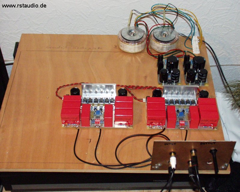
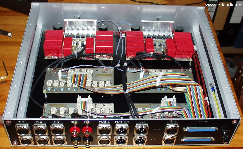
The following image shows the initial assembly of the prototype as a breadboard setup. The mains voltage is supplied via the terminal blocks at the rear right. To the left of these are the two toroidal transformers (2x 50VA), which are easily recognizable. In front of them are the two power supplies, whose AC input is located at the rear and DC output at the front. In front of them are the two Aleph P preamplifier boards. The vertically mounted board features RCA jacks for the inputs and outputs. On the right side of this board is the potentiometer described above. I wired the audio signals using RG174.
Volume & Gain Settings
February 25, 2006
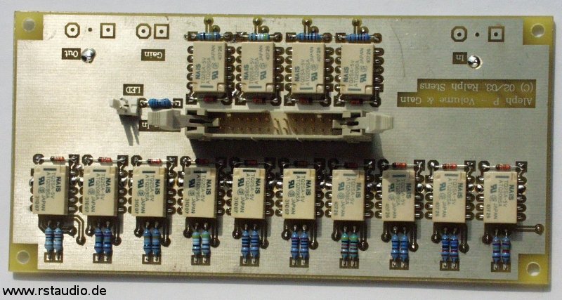
When setting the volume, I generally followed the design of the Aleph P, but I added two additional resistor values, increasing the number of bits from 8 to 10. This allows me to achieve an attenuation of approximately -60 dB. The 1% metal-film resistors used are 62Ω, 124Ω, 249Ω, 499Ω, 1kΩ, 2kΩ, 4.02kΩ, 8.06kΩ, 16kΩ, and 32.4kΩ. I purchased 100 units of each value and calibrated four of them to within 0.1% using the Agilent multimeter mentioned above. This ensures a very high degree of alignment between the two signal paths and also between the two channels.
The two largest resistors in the voltage dividers (16kΩ and 32.4kΩ) are already on the same order of magnitude as the input resistances of power amplifiers. For this reason, the input resistance of the subsequent stage must be included in the calculation to accurately determine the attenuation (loaded voltage divider).
Four additional resistors on the board can be switched to adjust the gain. Resistors with values of 249Ω, 499Ω, 1kΩ, and 2kΩ are used. Combinations of these resistors can be connected in parallel. This allows for 15 different gain settings. Here, too, the resistors in both channels were compared against each other to ensure maximum consistency.
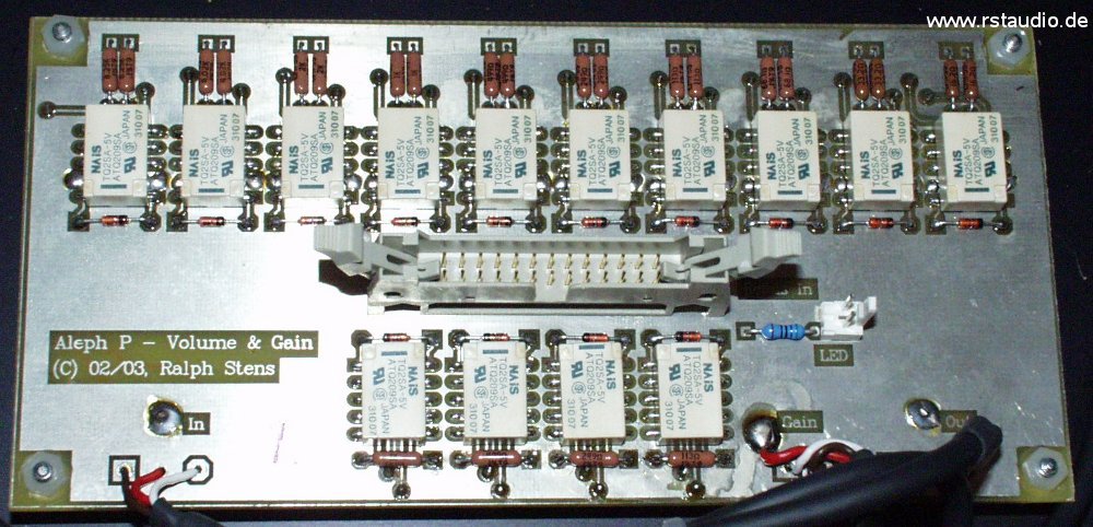
In the center of the board, the relay control signals are fed in via a 26-pin header connector. Although these signals only change when the volume or gain is adjusted, I made sure to keep the analog signals and control signals separate in the layout — hence the central placement of the connector. The board also features a connection for an LED, which I use as a power indicator for the analog amplifiers.
- Schematic Diagram of Voltage Divider and Gain
- Relay Control
- Board Assembly
Contrary to the specifications in the parts list, I used 1N4148 diodes as free-wheeling diodes. They are sufficiently rated for the relays used and are also smaller than the specified 1N4001 diodes.
Input Selection Switch
February 25, 2006
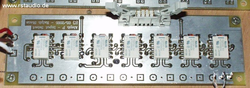
The inputs are switched using relays. There are five differential inputs available. Additionally, a tape deck with rear-tape control can be connected. A unique feature is a relay that can connect the negative channel of the currently active input to ground. This makes it possible to connect a device with a single-ended output without having to manually short the negative signal path.
- Schematic Diagram of the Input Selection Switch
- Board Assembly
The same applies here as above regarding the reverse-bias diodes used.
Microcontroller Board
February 25, 2006
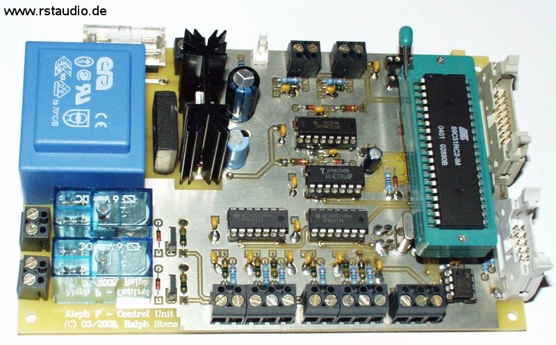
The preamplifier is controlled by a microcontroller. Two rotary encoders with push buttons serve as the control elements. A two-line LCD display, each line containing 20 characters, is used to display information. Additionally, the board features an input for an IR remote control.
The central component of the circuit is the AT89C51RC2 microcontroller from Atmel. I selected it because of its 32kB of internal program memory and 1kB of RAM. The controller’s clock signal is generated using C1, C2, and X1. R1, D1, and C3 form the controller’s reset circuit. The I²C bus EEPROM 24LC64 provides 8kB of non-volatile memory for the permanent storage of parameters and data. The I²C bus is connected to the 10-pin header PF2. LK1 is connected to the IR detector of the TSOP17xx family. The 16-pin terminal block PF1 is used to connect the backlit LC display. The contrast of this display can be adjusted either via the 10-turn trimmer P1 or via the digital potentiometer DS1867 (these components are optionally installed). The backlight can be turned off using Q1.
As mentioned above, the board features two rotary encoders with pushbuttons as control elements. The first rotary encoder is connected to LK5 and debounced using components R6 through R11, C8 through C10, and IC5A through IC5C. The signals processed in this way are then transmitted directly to the microcontroller. The second rotary encoder has an identical circuit for debouncing the buttons (R12 to R17, C11 to C13, and IC7A to IC7C). Additionally, the processed output signal A from this rotary encoder is further processed by the two monostable multivibrators (74HCT123 – IC8A, IC8B). These generate two signals, each approximately 0.1ms long, whenever signal A changes (during a rising or falling edge of A). The two output signals from the multivibrators are combined using an XOR gate (74HCT86, IC6D) and inverted by IC5D (74HCT14). A signal is available that has a high level in the idle state and outputs a 0.1ms low pulse when A changes. This rotary encoder can thus be evaluated via an interrupt. Two pushbuttons can be connected via LK7 and LK8, which in turn are debounced by R20 to R23, C16 to C17, and IC7E to IC7F.
Q2 and Q3 are used to switch the two relays, REL1 and REL2. This makes controllable mains voltages available at the controller’s terminals LK2 and LK3. An LED can be connected to J10, which lights up when operating voltage is present. LK1 is used to connect the mains voltage (230V/AC). The components F1, TR1, BR1, IC4, and C4 through C7 form the operating voltage supply for the controller board.
- Schematic Diagram of the microcontroller
- Schematic Diagram of the Encoder
- Schematic Diagram the operating power supply
- Board Assembly
The image shows the assembled microcontroller board with a Textool type socket. The digital potentiometer is not installed, as the contrast is adjusted here using a manual potentiometer.
I²C Bus Relay Driver Board
February 25, 2006
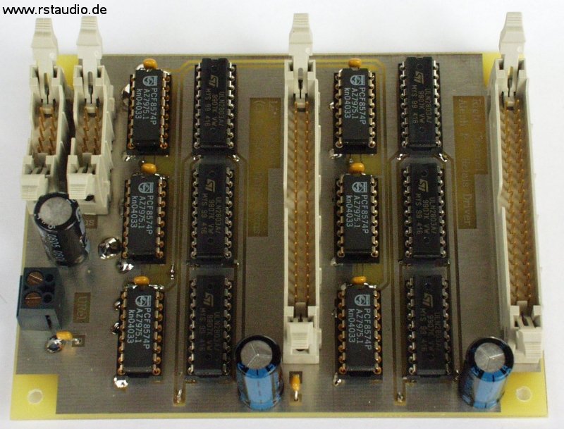
There are a total of 42 relays for audio processing in the preamplifier. To keep the board size within the dimensions of a Eurocard, I moved the relay drivers to a separate board and implemented digital control via the I²C bus.
The board is connected to the microcontroller board via PF1 or PF2. The operating voltage for the I²C bus port modules PCF8574 (IC1, IC3, IC5, IC7, IC9, and IC11) is also supplied by the µC board via PF1/PF2. The addresses of the port modules are hardwired. Since these modules are not capable of switching larger loads, the ULN2803A Darlington driver arrays (IC2, IC4, IC6, IC8, IC10, IC12) are connected downstream. The operating voltage for the relays is connected via LK1. The advantage of separating the two operating voltages is that the coil voltage of the relays can be freely selected. Additionally, the power supply for the μC board can be significantly smaller.
The circuit boards for volume/gain and input are connected to the 40-pin male connectors PF3 and PF4. The signal distribution on the connectors is designed so that the 40-pin ribbon cable can be spliced and a 26-pin and a 10-pin terminal block connector can be crimped onto the ends (starting at 1). The purpose of this approach is to house the electronics in separate enclosures and to connect the relay drivers to the actual boards via 37-pin Sub-D connectors.
- Schematic Diagram of the I²C-Bus Relay Driver Board
- Board Assembly
Power Supply for the Relays
February 25, 2006
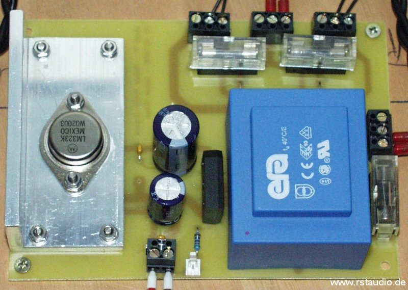
The relays are powered by the 3A fixed-voltage regulator LM323 (IC1). Even if all 42 relays were activated simultaneously (which is impossible), this regulator would have sufficient capacity. The 16VA transformer and the 8A bridge rectifier used are also more than adequately rated. This board also features fuses (F2 and F3) for the primary voltages of the toroidal transformers in the audio power supplies (input LK2, outputs LK3 and LK4). It is also possible to connect an LED.
- Schematic Diagram of the Power Supply
- Board Assembly
Software Description
February 25, 2006
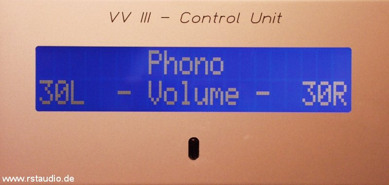
The description of the microcontroller briefly mentioned how to operate the preamplifier. The user has two rotary encoders with push buttons available for entering data. A two-line, 20-column LCD serves as the display.
After turning on the preamplifier, a welcome screen is displayed for a certain period of time. During this time, no operations are possible. The set time (60 seconds in my case) is required to allow the analog operating voltage to stabilize at its final value. Only after this time has elapsed is the last-activated input reactivated. The volume and gain settings are then adjusted (see below) — the output was deactivated until this point. Finally, the main screen appears, indicating that the preamplifier is ready for operation.
The first line displays the currently active input in the center. The second line shows the volume relay settings for each channel separately. These can be displayed either as numerical values ranging from 1 to the maximum number of settings, or in dB based on the look-up table.
The volume control is interrupt-driven. The volume can be adjusted at any time and from any menu item (see below). Each time the control clicks into a new position, the current relay combination for the selected volume is set immediately. Since the control can be turned in either direction without a stop, the software stops adjusting the setting once either limit is reached.
When the button on the volume rotary encoder is pressed briefly, the outputs are muted. However, if the button is held down for more than 2.5 seconds, the preamplifier enters standby mode. This disconnects the power supply to the relay. Whether the power supply voltage for the analog circuit is also turned off depends on the setting in the Standby menu (see below). When the preamplifier is in this operating mode, it can be turned back on by pressing the button again. This is indicated by the illuminated LED on the control module while the display is off. In addition, the LED on the audio module is no longer lit.
The inputs are switched via the Select rotary encoder. The corresponding switching operation is performed immediately after the rotation direction is detected and is also shown on the display. During switching, the entire configuration of the input is evaluated, and the volume as well as the relay for single-ended operation are switched according to the stored parameters.
Pressing the button on the Select rotary encoder opens the preamplifier’s configuration menu. The following menu items are available:
- Tape Input
- Gain
- Mute
- Balance
- Start Volume
- Write Volume
- Input Config.
- Stand By
- Display
- Heat Up Time
- Software Version
- Delete Memory
- Quit
Turning the rotary encoder highlights the desired menu item on the display. Pressing the button then activates the menu item. Settings within each menu item are preselected by turning the encoder and confirmed by pressing the button again. The menu is then exited, and the program returns to the main screen.
Tape Input
This menu option allows you to enable or disable the tape input. When the tape input is enabled, this is indicated in the first line of the main screen. Unlike the standard display of the inputs, the activated input is additionally shown here, identified by a number ranging from 1 to 5. This informs the user which input is available for recording. Even when the tape input is active, a “normal” input can be selected using the Select rotary encoder.
Gain
The gain control adjusts the RG resistor (see above). This allows you to preselect the preamp’s internal gain. The four relays/resistors on the volume/gain board can switch between a total of 16 resistor combinations. However, the differences between some settings are only marginal, which is why I did not include them in the corresponding lookup table.
Mute
The Mute function mutes the output. This connects all volume control resistors to ground, thereby isolating the outputs from the preamplifier. Once Mute is deactivated, the settings naturally return to their pre-activation state (volume, gain, and balance).
Balance
There is no way to link the two stereo channels for balance adjustment via a potentiometer. The voltage divider at the preamplifier’s output, which controls the volume, is driven asymmetrically based on the balance setting. The balance can only be adjusted by a maximum of ±15 around the current volume level.
Start Volume
This section defines the volume and gain settings when the preamp is turned on. First, you must choose between “Last” and “Fixed.” With “Last,” the last valid level (from when the unit was turned off) is restored. If this setting is selected, the menu exits at this point. If “Fixed” is selected, a preset level is set, which is prompted immediately after selection. First, enter the value for Gain, followed by the value for Volume. The values are set using the rotary encoder and confirmed with the Select button. The respective setting starts with the last valid value.
Write Volume
In this menu option, the user can specify whether the volume should be displayed as a sequential number (starting with 1) or as attenuation in dB. The dB values are calculated based on the input impedance of the connected load (typically power amplifiers). For the Zen V4 power amplifier, for example, this value is 47kΩ.
Input Config.
Dies ist der aufwendigste Menüpunkt bei der Parametrierung des Vorverstärkers. Hier lässt sich ein vordefinierter Name dem Eingang zuordnen, zwischen Single-Ended- und Differenzbetrieb auswählen, eine Lautstärkekorrektur (Volume und Gain) einstellen und der Eingang deaktivieren. Ruft man dieses Menü auf, gelangt man zuerst zu einer Auswahl des Eingangs (Input 1–5, Tape). Ist der Eingang selektiert, gelangt man zum folgenden Menü:
- Name
- Diff./SE Input
- Level Correction
- Gain Setting
- Input on/off
- Quit
You can enter any name for the input. Each letter is selected using the rotary encoder and confirmed by briefly pressing “Select Enter.” Once all letters of the desired name have been selected, exit this menu by pressing and holding the Enter button for more than 2.5 seconds. You will then return to the main menu. The selected name will now be displayed on the main screen for this input in the first line, provided that the tape input has not been set (see above).
As mentioned above, the “Diff./SE Input” menu option is used to specify whether the input is single-ended or differential. If a single-ended input is selected, a relay is activated that connects the preamplifier’s negative input to ground (see above).
The next menu item takes you to the level correction setting. Here, you enter a correction value for the volume setting. When this input is selected, the current volume setting is automatically adjusted by the value specified here. This helps minimize volume jumps between inputs.
However, the default volume correction setting is determined by the gain setting. This adjusts the internal gain of the preamplifier individually for each input. Using these two parameters, you can precisely correct volume fluctuations between individual sources.
All inputs can be disabled. This is done in the “Input on/off” menu option. If an input is disabled, it is skipped during input switching. This allows you to easily remove unused inputs.
Press the “Quit” button to exit the menu. Each of the settings described here is saved immediately after you confirm them with the Select button.
Stand By
In standby mode, the microcontroller electronics remain active. The controller always cuts off the operating power supply to the relays. At this point, the user can choose whether to also cut off the analog power supply. If this supply is not switched off, a thermally stabilized operating point for the audio electronics is available immediately after the preamplifier is turned on. If the amplifiers are not switched off, the wait time upon power-up is also reduced, since only the power supply to the relays needs to stabilize, which happens much faster than that of the analog operating voltage.
Display
You can use the digital potentiometer here to adjust the contrast of the LCD display. The hexadecimal value currently being written to the potentiometer is displayed. Exit the menu as usual by pressing the Select button. The current value is saved and will be active the next time the preamplifier is turned on.
Heat Up Time
Here, two times are entered in seconds. The first time, “Cold Time,” is the amount of time that elapses after the mains power is turned on until the preamplifier switches to normal operation. The second time, known as “Warm Time,” is the corresponding time after a standby period during which the analog operating voltage was not turned off (see Standby).
Software Version
The current software version, as well as the date and time of the compiler run, are displayed here for ten seconds. No further action is required after selecting this menu item. Following the version number is a letter (currently A or RS) that provides information about the possibility of conditional compilation of the software. The volume and gain settings, as well as the stored wait times, are saved in a separate file and are integrated on a user-specific basis.
Delete Memory
If you select this option, you will first be asked whether you really want to erase the memory (No/Yes). The default answer is “No.” You must confirm your answer using the Select button. If “Yes” is selected, all settings stored in the EEPROM will be deleted. This will restore the configuration to its state after the first power-up. If “No” is selected, the menu will be exited without further action.
Quit
This menu option allows you to exit the menu without changing the configuration.
If you use the digital potentiometer to adjust the display’s contrast, there is, of course, a risk that the current setting will cause the display to go blank. This also makes it impossible to make any further changes to the contrast, since the display is needed to access the contrast adjustment menu item in the first place. There is a way to reset the parameters to their default values to resolve this issue. After the preamplifier has been turned on and is in normal operating mode (the LEDs on the audio module are no longer flashing and the relays have been activated), you can re-enter the menu by pressing and holding the Select button for more than 2.5 seconds. However, default values are now set for some parameters. The display should now show a visible output again.
Commissioning of all Components
February 23, 2006
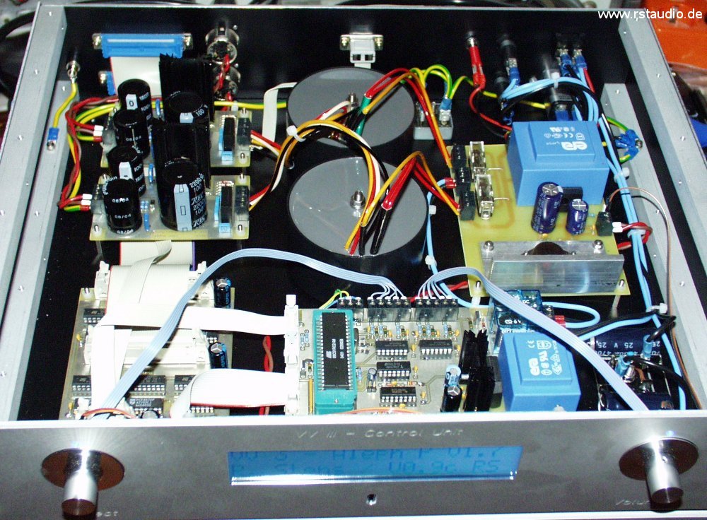
Once all the components, including the initial software versions, were available, I expanded the breadboard setup described above. The wiring was done using standard “hardware store” wire and wasn’t neatly laid out — in short, it looks a bit rough. Everything is crammed into a very tight space. Nevertheless, the sound quality is excellent: no noise, no hum …
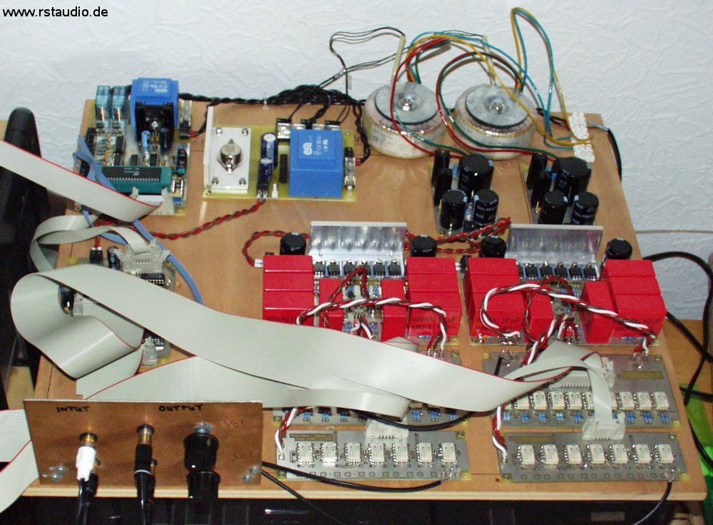
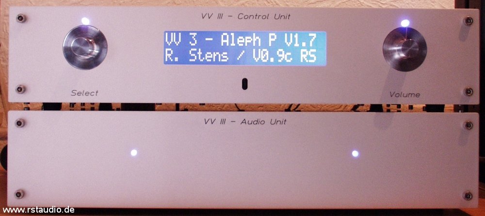
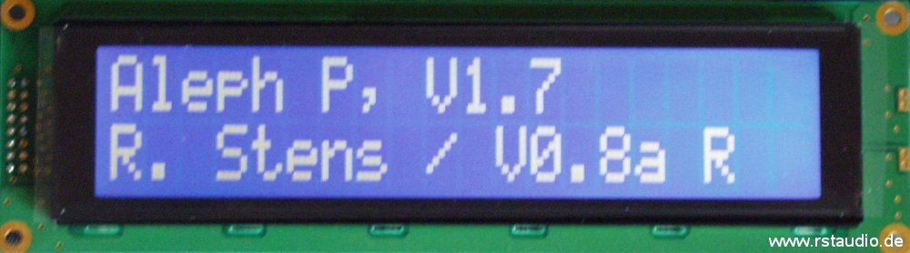
The display is missing from the photo above because it’s currently just lying around. You can see the 16-pin ribbon cable extending to the left, out of the frame. So here’s a photo of the display showing the startup screen during the stabilization phase (the software version shown is no longer the latest).
Enclosure
May 15, 2006
The design is inspired by the current X1 preamplifier from Pass Labs, though it does not replicate the intricate design of the front panel. The controls also differ, featuring a second rotary encoder instead of four buttons. However, the electronics are still housed in two separate enclosures, arranged as follows:
- Controller Enclosure (Control Unit)
- μC Board
- I²C-Bus Relay Driver
- Power supply for the relays
- 2x Toroidal transformers for analog operating voltage
- 2x Power supply for the analog electronics
- Controls & Display
- Mains power supply
- Ground Connection
- Connections to the audio enclosure
- Audio Enclosure (Audio Unit)
- 2x preamplifier
- 2x Volume and Gain Settings
- 2x Input selector switch
- all necessary external audio connections (XLR & Cinch)
- Connections to the controller enclosure
The front panel and rear panel are screwed together using four 345mm x 15mm x 15mm aluminum bars through M5 blind holes at the top. The other case components are then attached to these profiles using M3 screws.
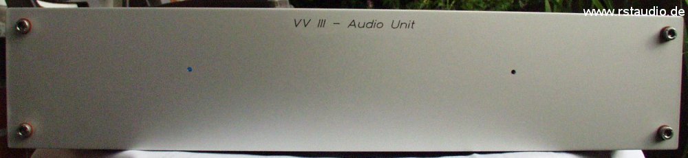
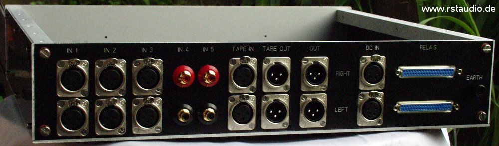
The photo shows the front and back of the empty audio enclosure without the top panel. All the necessary jacks are screwed into the back panel. I deliberately chose not to blacken the silver edges of the black enclosure parts, as I like the “technical” look that results without this blackening.
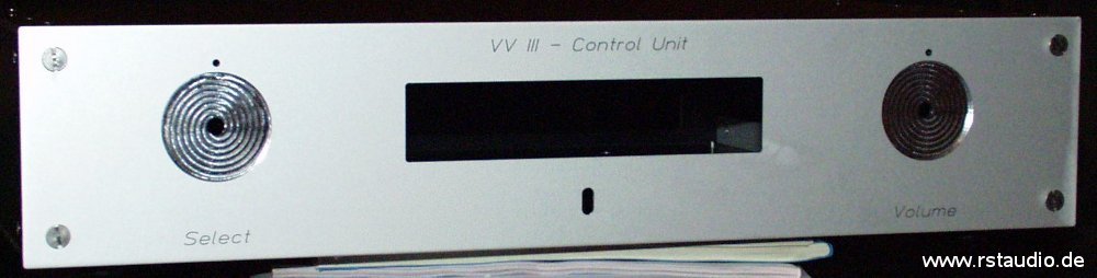
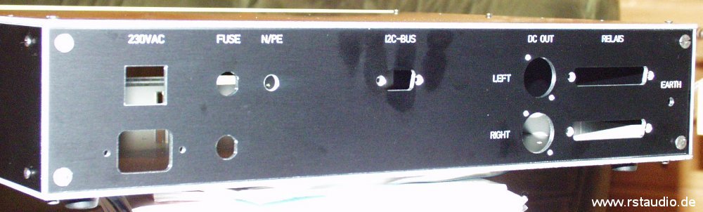
Here you can see the empty control housing from both sides. On the front panel, the two circular cutouts for the rotary knobs and the cutout for the display are clearly visible. Below that is the opening for the IR receiver. The rear panel features cutouts for the AC and DC power supplies, as well as Sub-D connectors for connecting the relays.
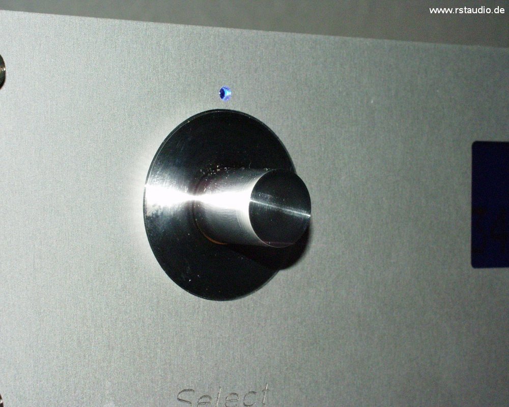
Here’s another photo of one of the two knobs. Making it wasn’t exactly easy, since the 1mm thin outer ring had to be turned. The result turned out truly beautiful. I’d like to extend a special thank you to Enrico V., who sacrificed part of his weekend to make this happen.
Finally, I must (once again) mention Enrico V. and, in particular, Rudolf B. They worked hard on building the cases and provided me with invaluable advice and assistance on many details. Without them, these beautiful cases would certainly not have come into being in this form.
!!! Thank you so much for that !!!
The joy of seeing the finished Aleph P makes the joy of music take a back seat, at least to some extent.
Wiring the Preamplifier
March 4, 2006
I have laid out the wiring in three schematics. The first schematic shows the wiring for the 230 V AC system. This wiring applies exclusively to the control unit. The signal wiring inside both enclosures is shown in the second and third schematics.
The 230V/AC system is not a simple point-to-point wiring configuration. It also includes the connection of the audio grounds (left and right) to earth, as well as the DC filter. Bridge rectifiers are used in both sub-circuits.
The AC voltage enters the device via the mains filter J1 and the two fuses F1 and F2, and is then switched by the two-pole switch S1. The DC filter (BR1, C1, C2, and C3) removes any DC voltage components from the 230V/AC voltage, thereby reducing the load on the two audio transformers (Schuro part number V-RKT-MS-SW 50.30). The bridge rectifier is wired such that two diodes are connected in series, and these two series circuits are connected in anti-parallel. This results in a maximum voltage of 1.2V across the capacitors. The voltage is low enough that the electrolytic capacitor, even if connected with the wrong polarity, will not be damaged (however, at least 25V types should be used).
The two audio grounds are each connected to earth via one half of the second bridge rectifier (BR2). Here, two diodes are connected in anti-parallel. For each channel, a resistor (5.1Ω) and a capacitor (100nF) are also included. Thus, both grounds are connected to earth potential. However, as a rule, no current flows between the grounds and earth. In the event of a fault, only the low breakdown voltage of a single diode needs to be overcome.
The DS3 LED is connected between neutral (N) and ground (LED module for 230V/AC) and provides a direct visual indication of whether the neutral (N) conductor in the preamplifier is connected to the external L1 or N. This ensures that the mains voltage is correctly polarized. The LED is located on the rear of the housing. The two LEDs, DS1 and DS2, serve as visual indicators of the operating voltages for the μC board and the relay power supply. The analog power supplies for the actual preamplifiers are routed via XLR1 and XLR2.
The display is connected to terminal PF1 on the μC board. LK4 is the input of the infrared receiver IC1. The two rotary encoders are connected to terminals LK5 and LK6. A and B are the two outputs of the encoder signal, and C is the common reference point for A and B (GND in this case). The pushbutton is connected to D and E. PF2 is the I²C bus output of the µC board. This is connected to PF1 on the relay driver board. The 9-pin Sub-D connector for the external I²C bus on the rear panel of the enclosure is connected to PF2 on this board. PF3 and PF4 connect the two 37-pin Sub-D connectors for connecting the relays of the audio unit.
For the internal audio wiring, I use a two-conductor shielded cable (even for the single-ended RCA connections). The inputs and outputs on the rear panel of the audio unit are directly connected to the corresponding inputs and outputs on the circuit boards (nothing is screwed in; everything is soldered). While this does result in a slight loss of flexibility, it ensures that you get the best possible connection.
Of the 37 signals from the two Sub-D connectors (J1 and J2), 36 are required. I use crimp connectors for ribbon cables. These cables must then be split into two separate cables for “Volume/Gain” and “Input.” The signals are arranged on the connectors in a way that makes this as simple as possible. The two LEDs, DS1L and DS1R, are located on the front panel of the audio unit.
- Wiring of the Audio Unit
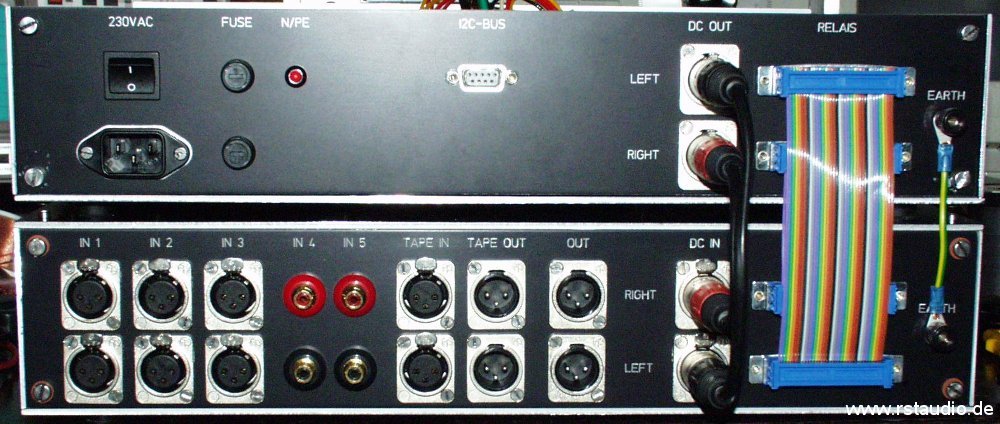
Here you can see the connections between the two enclosures. On the far right is the ground connection; to the left of that are the two ribbon cables connecting the relays (Volume and Input) to the relay drivers, as well as the connections to the DC power supply for the two preamplifiers via 4-pin XLR connectors.
Updates & Improvements
February 23, 2006
Of course, there’s always room for improvement. Especially when building a system, you often notice in hindsight things that could have been handled better.
September 7, 2005 / Volume & Gain
The “internal” gain of the Aleph P is determined by the total resistance RG. The lower this resistance is, the higher the gain. I permanently installed a 2kΩ resistor on the preamp board and replaced the 2kΩ resistors on the volume/gain boards with 124Ω resistors. This gives me the quietest setting when no gain resistor is engaged, and the loudest when all are in parallel. Additionally, a faint “pop” noise when switching the gain is eliminated when a resistor permanently maintains the connection between the two amplifier halves. With the original circuit, it could happen that both preamp halves were briefly disconnected during the switching moment.
September 23, 2005 / Volume & Gain
A discussion about the pros and cons of high-quality, non-magnetic resistors — which I felt hadn’t been satisfactorily resolved — made me curious to conduct my own evaluation. I purchased a set of Dale CMF-55-143 resistors (68.1Ω, 113Ω, 249Ω, 499Ω, 1kΩ, 2kΩ, 4.02kΩ, 8.25kΩ, 16.2kΩ, and 32.4kΩ) and installed them on both volume/gain boards. In the absence of a direct A/B comparison, the assessment of the results is, of course, somewhat questionable. However, I imagine I can hear an increased level of detail (e.g., a triangle in the background that I hadn’t noticed so clearly before). But as I said, this statement should be taken with a grain of salt.
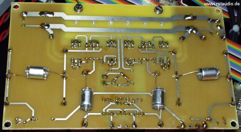
The blue metal-film resistor to the right below the pin header is the series resistor for the LED and has nothing to do with the audio signal, which is why no Dale component is installed at this location.
December 23, 2005 / Preamplifier
The quality of the coupling capacitors in the audio signal path is crucial to the performance of the preamplifier. For this reason, I attempted to further improve the already good coupling provided by the Wima MKP4 capacitors by soldering 10nF Styroflex capacitors (order number STYROFLEX 10N from Reichelt Elektronik) in parallel with the input and output capacitors. The sonic assessment is similar to that of using Dale resistors in the volume control — again, there is no way to perform a direct A/B comparison. However, the results are so good that I certainly won’t be removing the capacitors.
January 22, 2006 / Preamplifier
I’ve had a complete set of Dale resistors for the preamp boards lying around here for quite some time. I’ve also made a few changes to the board layout (rounded off the traces, added pads to accommodate electrolytic capacitors as coupling capacitors at the input and output). With this modification, I built the boards (Revision 1) with a full set of Dale components and Wima coupling capacitors. I removed the Styroflex capacitors that I had added on December 23, 2005, since I ultimately couldn’t hear any significant difference with or without them.
Now that the Dale components are fully integrated into the preamp’s audio path, the pros and cons are clear to me: The preamp has clearly come out on top, and the Dales will be a must-have for me in any final setup. Even though I haven’t been able to do a direct A/B comparison, the improvement is clearly audible.