Table of Contents
Introduction
23-02-2010
In February 2010, at the ACT Niederrhein Stammtisch (Analogue Currywurst Treffen) of the AAA (Analogue Audio Association), the wish arose to run an own Hiraga MC Prepre. Since I had always been interested in this preamplifier, no one had to ask me to start working on a design. After all, it is a very simple circuit and so a circuit board was quickly created.
Schematic of the Hiraga MC Preamplifier
24-10-2021
To describe the circuit, I would first like to show the original circuit by Jean Hiraga from L’Audiophile.
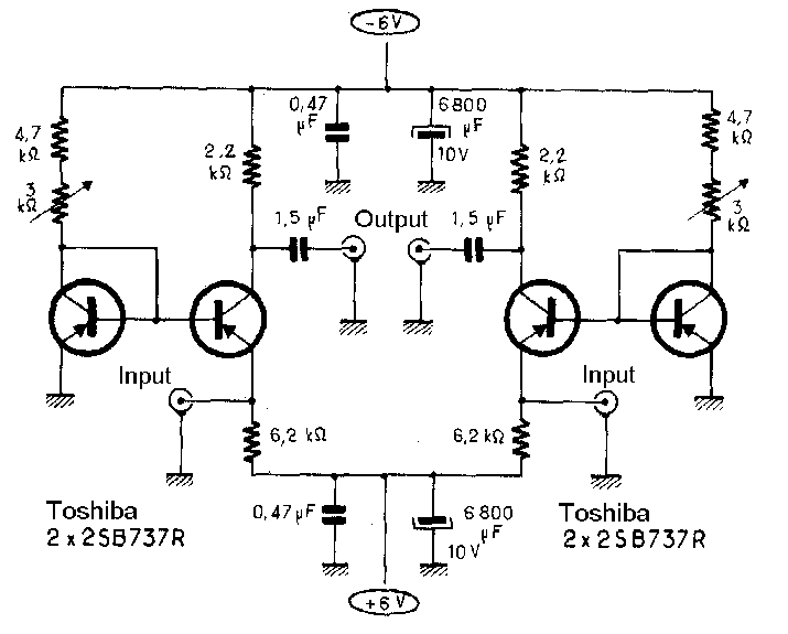
The specified transistors of the original circuit are now very difficult to obtain and so some replacement types are circulating through the net as recommendations, e.g. the TBC560 from Toshiba. However, according to a long-time user of this circuit, the BC560C is not the optimal choice – the recommendation here is 2SA1038 or 2SA1085 (thanks Anton), also pnp transistors from Toshiba. Since I had enough 2SA1085 in stock, the choice naturally fell on this transistor.
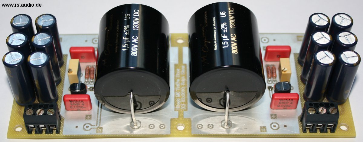
The capacitor at the output should have a very high quality as an audio coupling capacitor and so I chose a Mundorf MCap Supreme silver/gold at this point. As resistors I used the proven non-magnetic Vishay-Dale CMF-55-143 and Panasonic FC’s as electrolytic capacitors of the operating voltages.
- Schematic of my Hiraga MC Prepreamplifier
- Top Overlay of the Board
From a quantity of 50 pieces, I determined 2 pairs of approximately identical transistors by measuring the current amplification. The pairs were then – as you can easily see in the photo above – thermally coupled on the circuit board. To do this, I applied a thin layer of heat-conducting paste to the front surface of one transistor and then connected the two with a piece of heat-shrink tubing. During a first quick check on a laboratory power supply as voltage source, both inputs could be calibrated to a few µV with an Agilent bench multimeter.
Power Supply
24-10-2021
Most users of the Hiraga Prepre use batteries for the operating voltage supply. I did not want to go down this route for the time being and decided to use a shunt regulator. It is the first time that I use this type of voltage regulator in my circuits and so my experience of the behaviour of such a regulator was limited to the Spice simulation.
For the design, I largely followed a circuit suggestion from the following article:
- Shunt or Not
Are Waagbø
audioXpress, 02/08
I wanted to use a rather simple and completely discrete design of the regulator and so I decided to use the Simple Shunt Regulator with Constant Current Source.
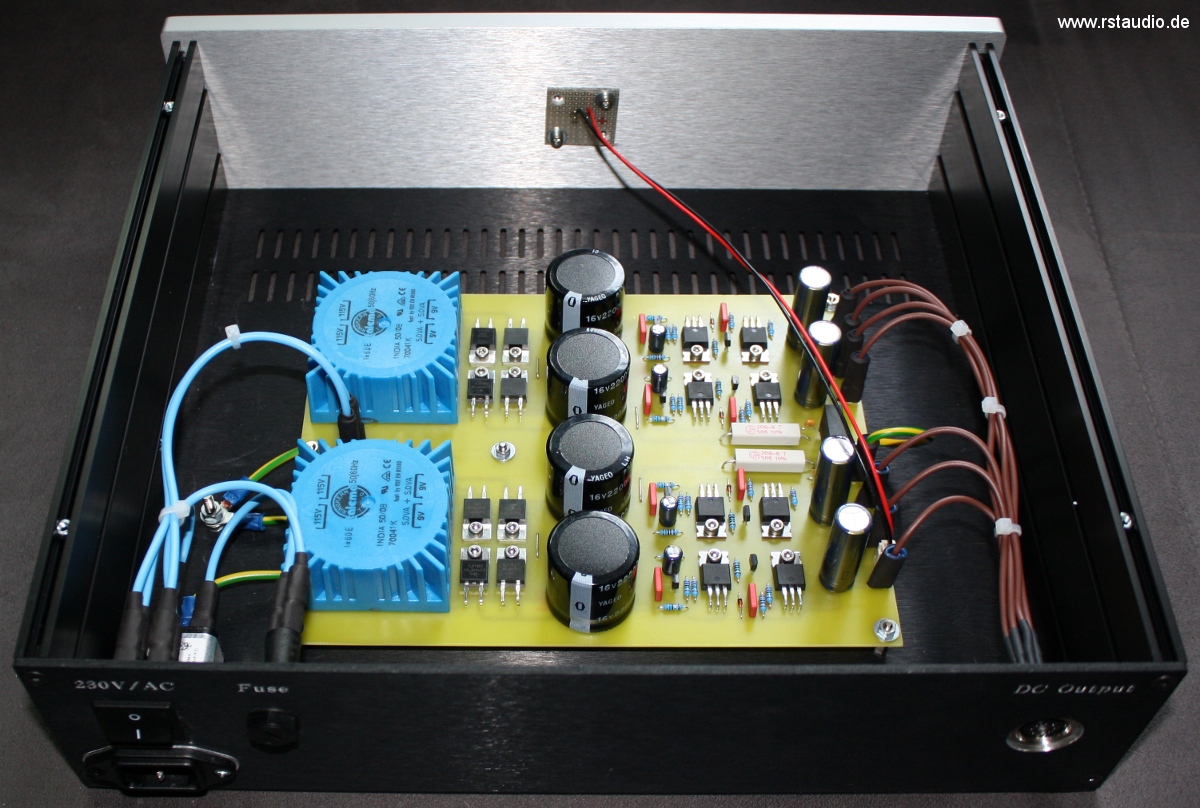
As always, the construction of the power supply is dual-mono. After the transformer, the discrete rectifiers built with Ultrafast Soft Recovery diodes and the first filter capacitors (4× 22000µF), current sources are connected that are designed for approx. 10mA. The Hiraga MC consumes approx. 1mA from the positive and approx. 2mA from the negative operating voltage and thus the current sources are far above the recommendations – about twice the current of the load – for the design with a shunt regulator.
At the output of the regulators are 3300µF Panasonic FC electrolytic capacitors. Following this, there are 4× 100000µF electrolytic capacitors supported by 10µF Wima MKP4 capacitors in the housing of the MC stage. On the circuit board of the Hiraga MC itself there are another 12× 2200µF Panasonic FC electrolytic capacitors. In the end, the total capacitance behind the regulators is nominally 439640µF – this may not be quite what J. Hiraga had in mind, but I think it is more than sufficient for a first setup. Moreover, the shunt regulator is housed in a separate case and could therefore easily be replaced by batteries.

An essential aspect in the decision against a supply with batteries is my experience with the Pass XOno. This phono preamplifier takes a very long time to reach a stable operating point and so I never switch it off – which is exactly what I intend to do with the Hiraga MC. The power consumption is so low that it is best to just let the amplifier run through and for that you need a power supply.
Assembly of the Enclosures
07-05-2010
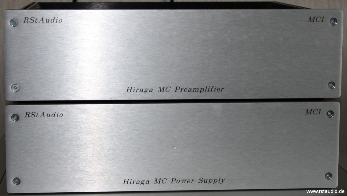
As indicated above, the entire Hiraga MC preamplifier spans 2 enclosures – audio and power. The enclosures are from HI-FI 2000, from whose portfolio I chose the Galaxy Maggiorato measuring 330mm × 280mm × 80mm (W×D×H) with a 10mm thick front panel.
The picture below shows the audio cabinet from the front – front panel not mounted. The PCBs with the 100mF electrolytic capacitors and the 10µF MKP4 are mounted on the two side panels. In front of the rear panel is the actual prepreamplifier.

Below you can see the housing with the shunt regulator.
On the back of the preamplifier are the Cinch inputs and outputs, the connection for the earth cable of the tone arm / turntable, an earth connector and a seven-pole DIN connector for the supply of the operating voltages. The switch on the left side switches the connection for the ground cable either to the ground of the operating voltage or to the supplied earth.
On the power supply housing there is of course an input connector for the 230V/AC supply, a power switch and a fuse. On the right-hand side there is a seven-pin DIN connector through which the operating voltage is output.
