!!! Don’t Ask for Schematics !!!
As long as Nelson Pass / Wayne Colburn don’t publish this schematics, I also won’t gave it away. I don’t want to compromise the commercial success of these wonderful preamplifiers.
Table of Contents
- Introduction
- Control Module
- Microcontroller Board
- Power Supply for the Control System
- Power Supply for the Audio Modules
- 230V/AC Supply of the Preamplifier
- Remote Control of the Preamplifier
- Audio Module
- Assembly of the Cabinet
- Modifications and Improvements
Introduction
2012/11/08
Although I’m tonally very satiesfied with my preamplifier (X0.2 and XOno) I thought however since a longer time about a redesign. In particular the sectioning of the components over the cabinets and a new designed control system with additional possibilities of extentions let me 2011 come to the conclusion to start this project.
In the middle of the project – the X0.2 boards are already assembled – I got the schematics of the new XP-10 and XP-20 preamplifiers from Pass Labs. Naturally I changed my plans directly and replaced the X0.2 line preamp with the XP-20.
Shortly before I start to assemble the XP-20 boards I had enough informations about the differences between the XP-20 and the XP-30 collected so that I was able to build also a XP-30 clone without having the schematics available.
With all my considerations and experience over the last years the following concept of the VV5 preamplifier was evolved:
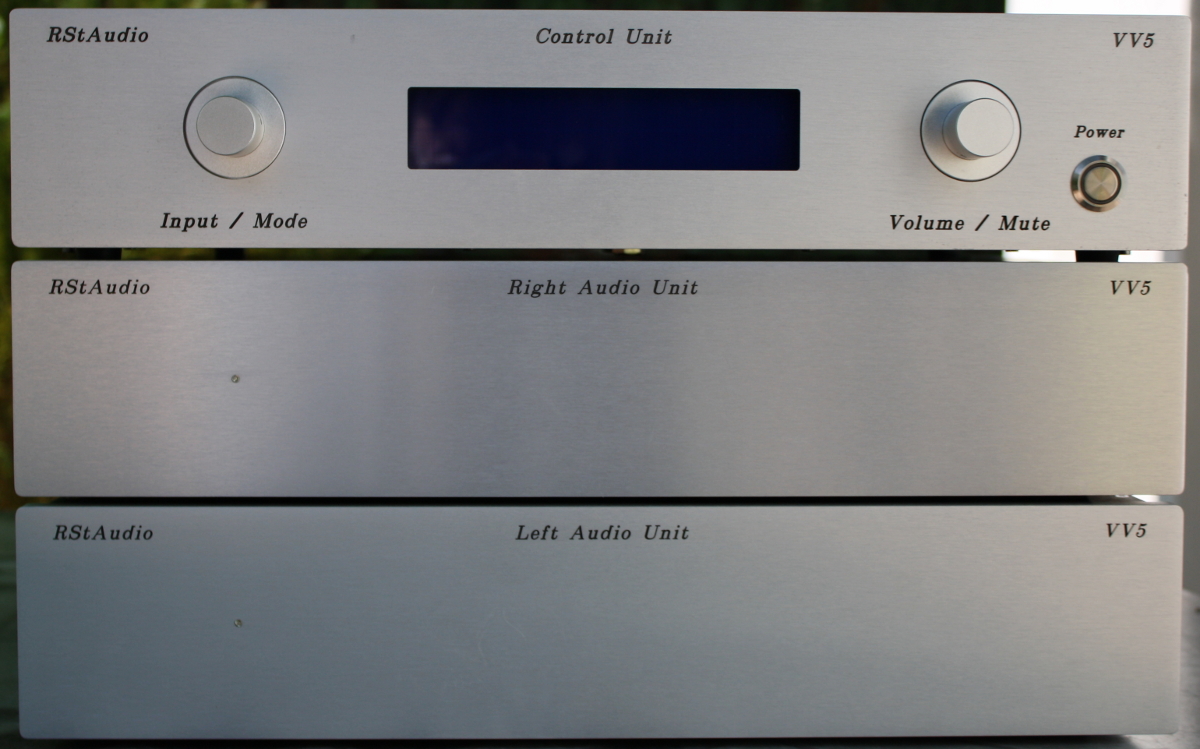
- Preamplifier with 3 cabinets
- left and right audio channel each in its own cabinet
- one channel consists of a XP-30 and a XOno replica
- an extra board with a relays switching for the inputs and outputs
- all inputs and outputs with symmetrical and single ended connectors
- additional cabinet with a µC board and a dual mono power supply
- Line preamp with a Pass XP-30 replica
- XP-30 line preamp incl. the single ended output stage
- no input switching on the board
- voltage regulator pluggable with an extra module
- space for different output coupling capacitors
- Phono preamp with a Pass XOno replica
- most of the DIP switches in the XOno replaced with relays
- additional input with a second MC stage
- voltage regulator pluggable with an extra module
- space for different output coupling capacitors
since 2013/05/09 the VV5 replaced my VV4 / X0.2 clone
I expected an improvement of the audiophil characteristics between the X0.2 and the XP-30. The X0.2 is definitely a really good preamplifier and I have heard very satiesfied music with it over several years. But I have not expected that the differences between both preamps are so considerable. The audiophil resolution and the richness of details are simply indescribable. Also the XOno benefits more than I expected from the new power supply – and the coupling capacitors (?). All in all a big step which I’m more than satiesfied with.
I exchange the Maxim DS1882 volume boards with the NJR MUSES72320 boards on the 3rd of October 2013. I fully understand now the decision of Wayne Colburn for the use of these chips in the XP-30 and my advice for the DIY community is to use this digital potentiometer also. The improvements are more than obvious.
Control Module
2012/11/07
This module serves as power supply and control for the audio modules. It encounters as the only module of the preamplifier with 230V/AC and consists of the following components:
- 230V/AC power supply input with a line filter
- Detection of the correct line phase
- 2 Transformers for the power supply of the audio modules
- unregulated power supply for the audio modules
- Transformer and power supply for the control circuits
- Microcontroller board for the control of the preamplifier
As the user interface I used again two rotary pulse encoder and a LC display. Additionally the preamp got this time a remote control so that I can operate all functions of the preamp direct from the listening place. The software certainly based on that of the Aleph P and X0.2.
Microcontroller Board
The microcontroller board and the display is one unit in this project and mounted direct behind the front panel. As in my other projects I used again a controller of the x51 family from Atmel. This time however I took the AT89C51ED2 in a PLCC44 case. This circuit has 64kByte of rewritable program storage and an in system programming (ISP) with the help of a boot loader over the standard seriell interface. This gives the possibility to bring new code on the finished preamp without a lengthy disassembling.
As I described above the user interface consists of two rotary pulse encoders from Alps and a 2×20 LC display from Electronic Assembly with 12.7mm high letters – as in the X0.2 and the Aleph P. This time I used also an additional push button to switch on and off the preamplifier – pricely I only switch the power supply of the µC board.
For the communication with the audio modules I used exclusively – with one exception – an I2C bus with a complete potential separation between the digital and analog circuits. Directly on the µC board a 64kBit EEPROM and a temperature measurement chip are connected also to this bus.
As a special feature this µC board has a second separat I2C bus which is completely independent from the first. This bus is intended for future external extensions.
Contrary to my other designs this board has also connections for 16 push buttons, 12 LED’s and 4 relays. Herewith additional or alternative operational concepts besides the rotary pulse encoders are possible.
Part of the LED outputs I have in use to drive external optocoupler mounted in the digital input of my Motor Driver. The driver is informed about the pick-up system which is actual in use – a number between 1 and 5 – if one of the phono inputs are switched on (see below). Of course both devices – VV5 and Motor Driver – have to parameterised in the same way.
As with my other preamps an IR receiver TSOP1736 is integrated in the system. In contrast to the predecessors I included this time a remote control in the operational concept – the software. For both of the two rotary pulse encoders there are 3 push buttons available at the remote control (left, right and enter). With this only marginal changes at most of the parts of the software are needed.
- Microcontroller
- I2C-Bus
- Rotary Pulse Encoder Input
- ISP Interface
- LED and Relay Driver
- Push Button Interface
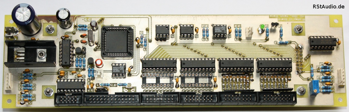
Microcontroller Board
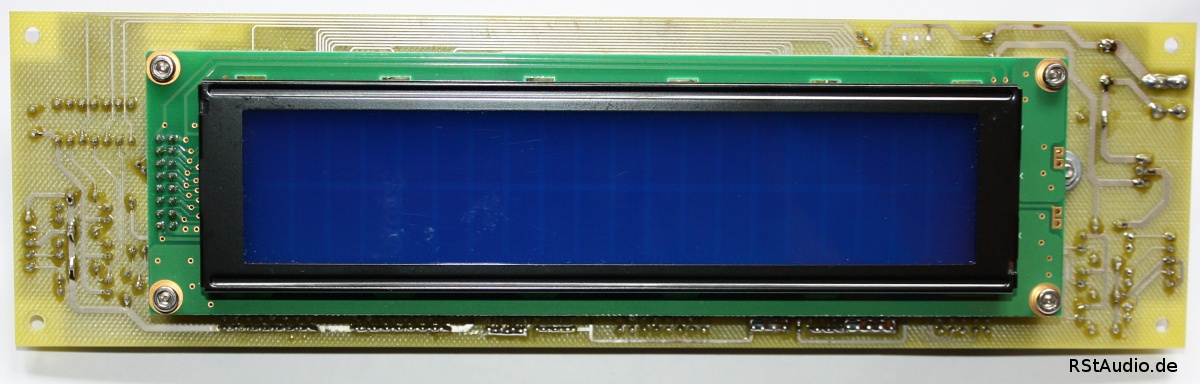
Display at the Rear Side of the Microcontroller Board
Power Supply for the Control System
The beginning of this board is as DC filter for the 230V/AC power line. It defends the transformers from unwanted DC fractions in the power line. At the output of this filter both audio transformers (external mounted) and the control transformer (mounted on this board) each with a fuse are connected.
The transformer for the control system is a 25VA toroidal transformer with 2× 9V secondary windings. At both windings a bridge rectifier and an electrolytic capacitor are connected. The boards provides two unregulated voltages. One voltage is used as a supply for the microcontroller board and the other for the supply of the relays. The second voltage is also used for the remote control voltage.
Both relays on the board are used to switch on and off this power supply board. With REL1 and an external connected push button the controller is switched on and with REL2 the controller is switched off. C8 is used that REL2 can hold itself a short time. With this it is guaranteed that a switch off is done under all circumstances – the system uses the same push button as above, but this time as a command for the microcontroller. It has to be avoided that the system directly switched on again.
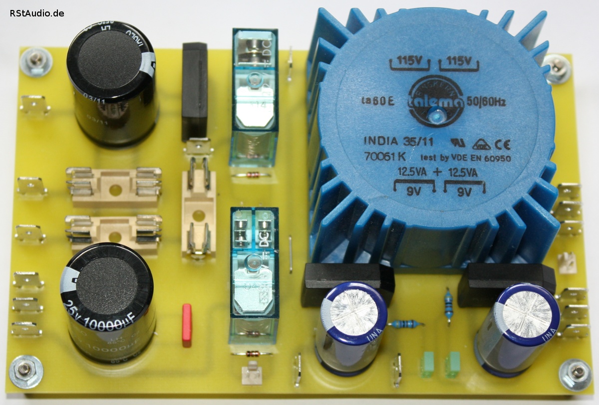
Power Supply for the Control System
Power Supply for the Audio Modules
The unregulated DC voltages for the audio modules are generated in the control module. Naturally I build dual mono supplies – one for every channel / audio module. Both supplies – with the exception of the transformers – are placed on one PCB. The only common point of reference for both power supplies is the connection of the left and rigth ground via a resistor and two antiparallel connected diodes to ground.
One power supply consists of a discret bridge rectifier with Ultra Fast Soft Recovery diodes from International Rectifier (HFA08TB60), a CRC filter with 4× 10000µF and 2× 3.3Ω/2W resistors. The following stage is a capacity multiplier with small power bipolar transistors. After this stage the DC voltages for the phono and line preamps are provided to the output connectors via a RC filter (2× 1Ω/2W & 2× 2200µF).
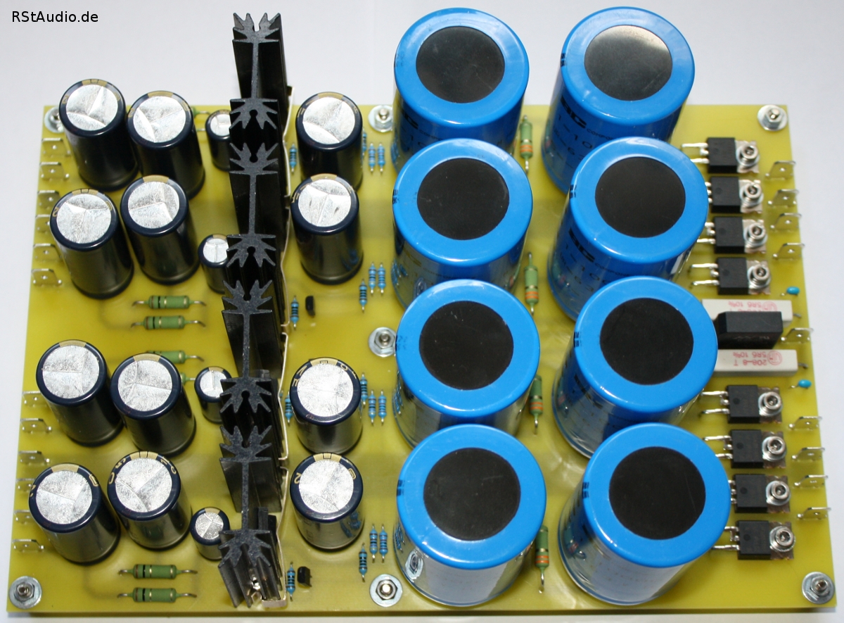
Analog Power Supply
A part of this circuit you also find on the original schematics of the XP-20. Therefore I will not make my schematics public too.
230V/AC Supply of the Preamplifier
On the back side of the Control Module the main socket with an integrated switch and fuse is mounted. Only with this switch the preamp can completely switched off. In the normal case the switch is on and the analog circuits are in operation. The next circuit after the main socket is a phase detection circuit for the correct phase of the power line, thereafter a 3A line filter from Schaffner and than the PCB with the DC filter and the power supply for the digital circuits (see above). The primary windings of the two 125VA toroidal transformers for the supply of the analog parts are connected to this PCB too.
The detection of the correct line phase of the mains plug is of course not done automatically. During the wiring of the toroidal transformers I measured the phase of the primary and secondary voltages of both transformers and wired them in the same way. Thereafter I measured the voltage between both analog grounds and earth, of course without the ground / earth connection plugged in. I wired the circuit for the phase detection than in such a way that I get a control signal to the microcontroller every time the mains plug is plugged in in the wrong way – with the higher voltage between the grounds and earth. The software gives a warning message to the user in that case.
Remote Control of the Preamplifier
At my two last Preamplifiers (Alpeh P and X0.2) I implemented the needed hardware for a remote control, but never in the software. For the VV5 the remote control was an inherent part of my functional specification.
I implemented a remote control with a RC5 code around the transmitter circuit SAA3010 and the receiver TSOP1736. The receiver is direct connected to the J1 connector of the microcontroller board (see above). I’ve set up the remote control with 9 switches
| Volume – | Mute | Volume + |
| Select Left | Enter | Select Right |
| Power Off | Reserve 1 | Reserve 2 |
At last I emulate the function of the rotary pulse encoders with the switches of the remote control. This simplifies the remote control functions in the software of the preamp.
The remote control sends the RC5 standard address (16) for preamplifiers. Also the Volume and Mute functions sends the standard command for preamps. The other functions uses free commands. For the change of the volume every commercial remote control for preamps shall work (e.g. the remote control of my CD player which has volume functions for a preamp integrated).
Audio Module
2012/11/15
This module comprised all audio circuits for one channel and therefore two of this modules are needed for a stereo preamplifier. One audio module consists of the following components:
- Replica of a XP-30 line preamp
- Replica of a UGS6 module as a basis for the line preamp
- XOno replica with diverse modifications and improvements
- Additional second XOno MC input
- CLC filter for the unregulated DC voltages
- Voltage regulator modules for line and phono
- Relays board to switch the inputs and outputs
- I2C bus board to control the audio module
XP-30 Replica
I have the schematics of the first version of the XP-20 with the digital potentiometer Maxim DS1802 available. After the intensively study of this schematics, the readings of test reports of the XP-30 with detailed view of the photos from the inside of the preamp and different comments on the forums I had so much informations carried together that I could start the implementation of a XP-30 replica.
The audio circuit of the XP-30 differs in some fundamental points from the XP-20. The core of the circuit – the UGS6 module – however is the same in both preamps. Mainly in the XP-30 an other chip for the volume regulation and at the output additional buffers are in use.
The unregulated power supply is essentialy the same, the XP-30 however has two transformers – which is common in my preamp designs. It is a true dual mono installation – also with regard to the 3 cabinets.
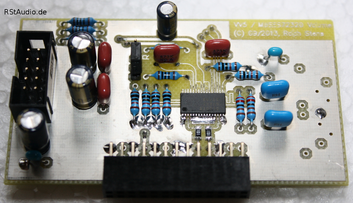
The MUSES72320 was at the start of the development of the line preamp not available in small quantities for private persons and so I have started with the volume chip from the second version of the XP-20 (Maxim DS1882). For an easy replacement of that chip I set the complete volume circuit on an extra board.
The volume range of the DS1882 contains 63dB, the XP-20 however has 83dB. This is achieved with an additional switchable 20dB damper. This voltage devider is located directly behind the input of the board and causes a dramatical change of the input impedance. To avoid that I decided to install a buffer in front of that damper. With this buffer I’ve got a constant input impedance, allthough I had a volume range of over 80dB with the Maxim chip.

Volume Board with Buffers, 20dB Damper and DS1882
Such an effort is not necessary with the MUSES72320. This chip has a damping factor of over 100dB with a resistance of 20kΩ. This chip can be directly placed at the input of the line preamp without an additional buffer or damper and you get anyhow an acceptable and largely constant input impedance.
Volume Board with MUSES 72320
In the data sheet of the MUSES72320 you can find the specification of the overall resistance with a minimal value of 13kΩ and a typical value of 20kΩ. These are remarkable deviations and therefore I design an additional resistor network to compensate different values between the channels – on the photo above the unpopulated part on the right side. From the 10 chips I own I select 2 at random and solder them on the PCB’s. At least I measured a difference of 0.008dB of the overall gain of the line stage between both channels in the area down to -40dB which is the most important in my equipment.
An I2C bus is used for the digital control of the DS1882, the MUSES72320 used a SPI bus. For both serial buses I have placed as allways an electrical isolation between the audio and the microcontroller circuits.
As the active element of the preamp an UGS6 module is in use. I set it like the original on an extra board, but my board is a little bit bigger and I used normal resistors. As an additional small change compared with the original I used multi turn trimmer.
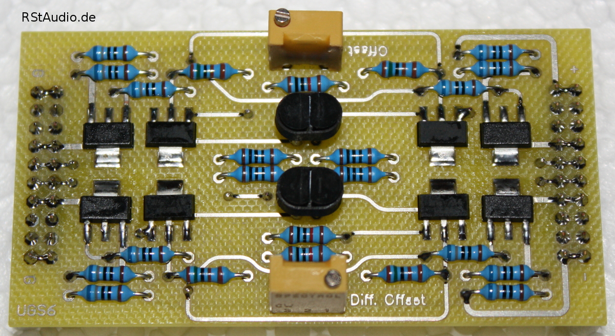
UGS6 Replica
At the output of this module an active buffer with small power MOSFET’s is used. To avoid a most likely offset voltage at the output from the UGS module coupling capacitors are placed behind the buffers. In contrast to the XP-20 – which uses Panasonic FC electrolytic cap in parallel with an ECQ capacitors – the XP-30 has 10µF MKP film capacitors, which are labeled with Pass Labs, in use. I assembled Obbligato Gold Premium capacitors at the output.
XP-30 Board without Add-On PCB’s
For the active and discrete voltage regulator of the XP-30 if build an own PCB, similar to the UGS module. Therefore I’m able to use another regulator technology by simply changing the boards. Against the original design, where standard integrated voltage regulators are used, I installed the same discrete regulators also for the supply of the analog voltage of the digital potentiometers. For the digital voltage supply I took an integrated voltage regulator from Linear Technology.
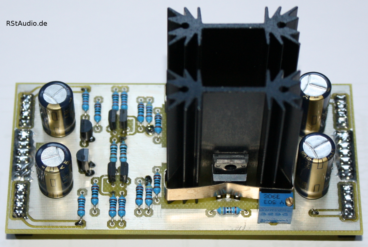
Discrete Voltage Regulator Board
I will not publish the schematics of my XP-30 clone – see above.
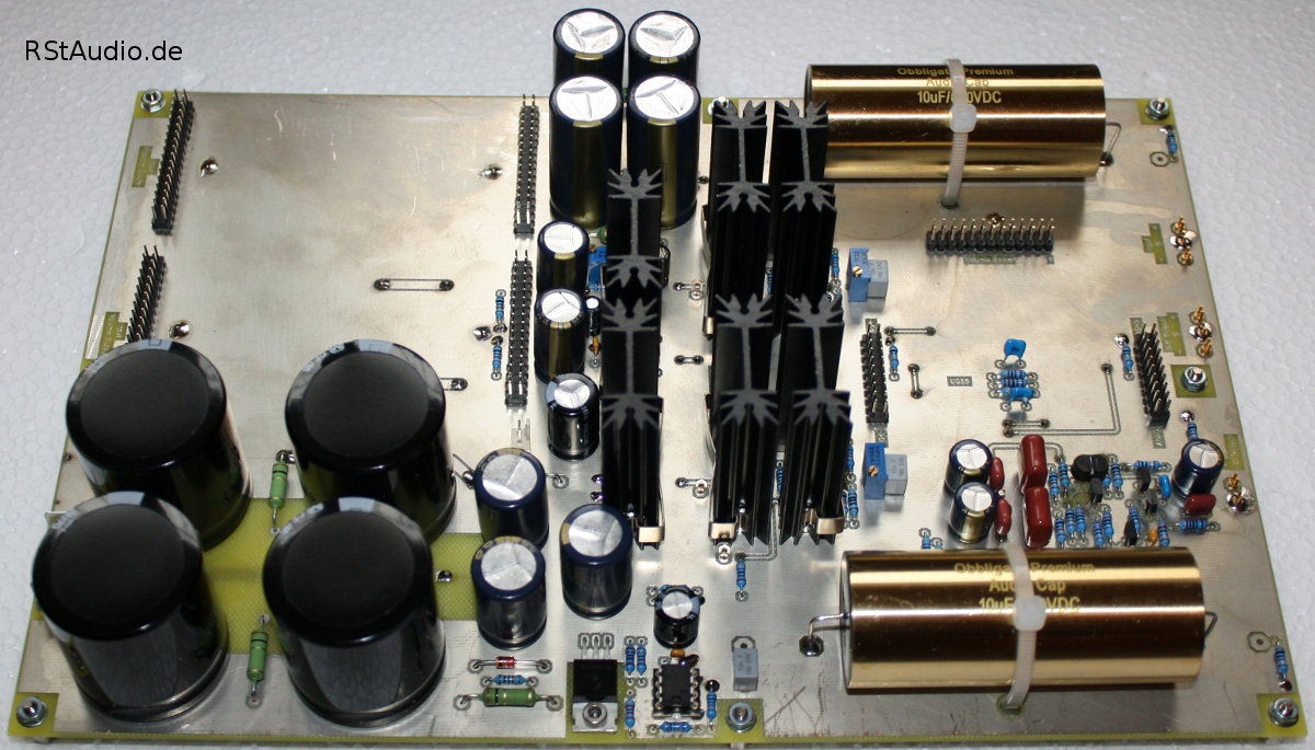
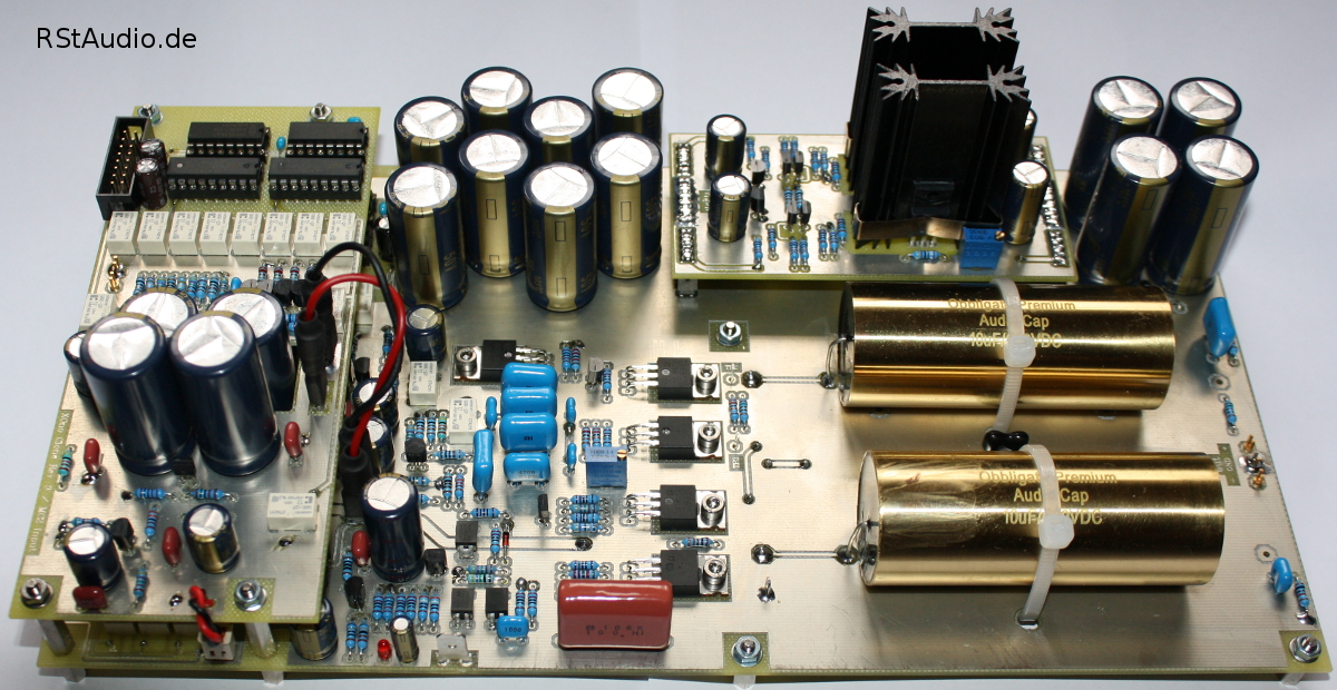
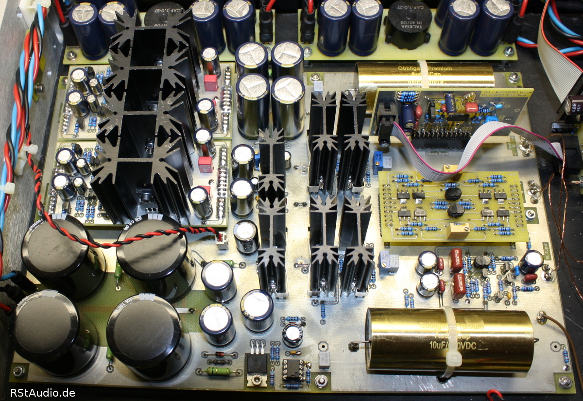
I will finish the description with a photo of the complete XP-30 clone inclusive all add-on boards (see below). On the lower left side the DC input is located with a CRC filter. Above you find both voltage regulator boards for the analog voltages of UGS6, buffer and SE output stage, as well as the regulator for the analog voltages of the digital potentiometer (DS1882 or MUSES72320). In the bottom center you find a circuit to assure that the analog voltage supplies earlier the digital potentiometer than the digital. This is very important for a failure-free operation of the DS1882. Direct above the digital voltage regulatores are placed. In the center of the right side you find the UGS6 board and directly on the left side of it the output buffers. Below the discrete operational amplifier for the single ended output can be seen. Above is the potentiometer board located (here with the DS1882). Left up and down outer side both output coupling capacitors are placed. It is enough space left for bigger types (e.g. Mundorf).
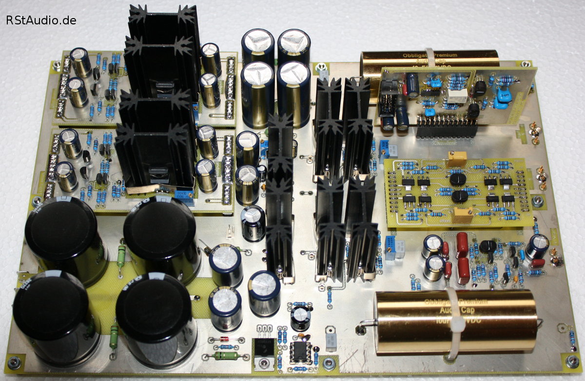
Complete XP-30 Board with all Add-On PCB’s
XOno Replica
This XOno based of course on the work and experiences I made with my XOno Clone over the years. I have two tone arms in use on my record player in the meantime, therefore I have the necessity that my new preamplifier provides me two MC inputs. I decided to set up a second MC input circuit of the XOno on an extra PCB and place it on top of the main MC input of the XOno.
Moreover I think it is not very practical to open the cabinet for e.g. changing the input impedance of the MC input. I therefore exchange most of the DIP switches with relays in the XOno design for my VV5. For the control of the relays I have once again an I2C bus in use which is inactive when nothing is switched – this garanteed that I have no interferences with the sensitive MC input stage. Additionally to the input impedance the amplification factor of the MC stage can be switched with relays.
Another relay in the MC stage is based on a suggestion at the AAA forum. It shorts the MC input to ground and shall be used to demagnetize the pick-up.
Of course I also have to take care that the 3 inputs of this XOno – MC1, MC2 and MM – can be switched with relays too. Thus the switching of the MC/MM at the DIP switch is also replaced. Apart from that I leave the DIP switch functions at the MM input as it is. This reflects my preference for MC pick-ups and asides from that I have only limited addresses / port circuits available on the I2C bus for the XOno (8× – two per MC stage).
Further bigger changes I made at the voltage regulator circuit. On the VV5 XOno board the same voltage regulator module is in use than on the XP-30 clone. I will start with the discrete regulator from the XP series, but I also want to give the shunt regulator which I used e.g. in my Hiraga prepre a chance.
I left a lot of space on the PCB for the coupling capacitors at the differential outputs and some types are predefined. This will give me some room for experiments in the future. As a start I installed Obbligato Gold Premium with a parallel connected Silver Mica capacitors. The coupling cap from the non inverted output to the inverter stage input is a 10µF Panasonic ECQ-E type – again with a parallel connected Silver Mica cap.
Schematics of the XOno :
XOno Board with plugged in Voltage Regulator Board
Schematics of the additional MC Input Stage :
MC2 Input Board
Finally a picture with the complete XOno Board for the VV5 preamplifier
XOno Board with MC2 Input & Voltage Regulator Boards
CLC Filter
Within the Control module the unregulated DC voltages for the analog ciruits are created (see above). In the Audio Modules these DC voltages are filtered again with electrolytic capacitors and current compensated chokes before the DC voltages finally reached the phono and line preamp boards (XOno and XP-30).
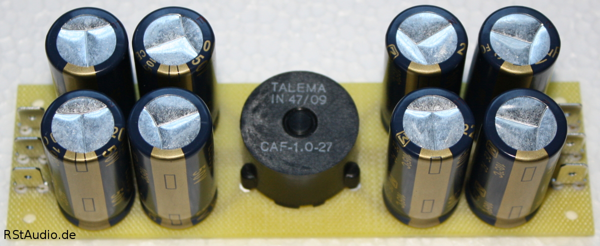
CLC Filter
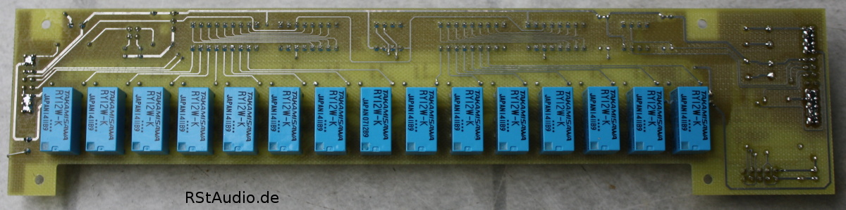
Input and Output Relay Board
At the design of the VV5 preamp my attention turns also on a concept to exchange parts of the preamp without bigger changes, e.g. the phono or preamp board. Therefore it was necessary to bring the input and output switches – in opposite to my VV4 – on an extra PCB. I decided to assemble this boards directly at the back planes of the Audio Modules to keep the wiring to the connectors as short as possible. The needed control circuits are located on a second board directly mounted on top of the relay board.
All inputs and outputs are switched with relays. Therefore the complete board is isolated against the microcontroller board. Switchable are
- 5× Line Inputs – the first input is wired internally to the XOno
- Tape Monitor Loop
- Fifferential / Single Ended Inputs
- Inverted Phase for the Differential Inputs
- Muting for Differential and Single Ended Outputs
- 2× Differential Outputs
- 2× Single Ended Outputs
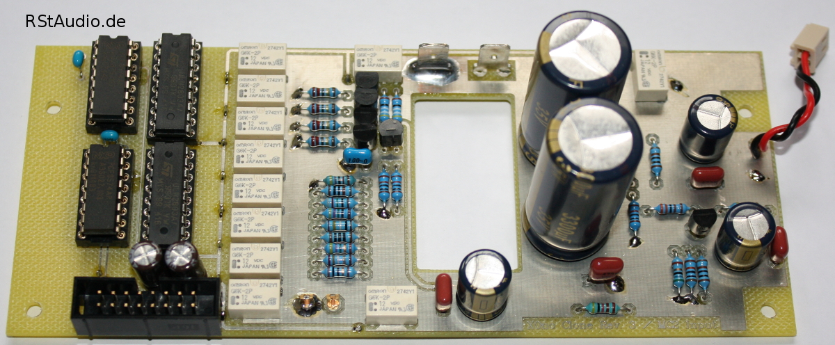
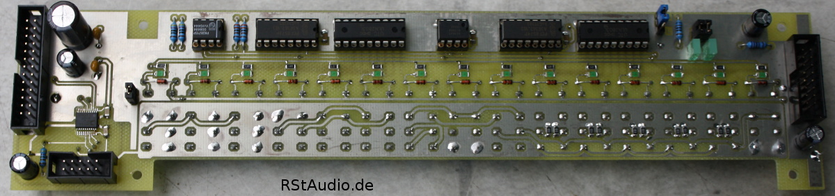
Schematics of the Input and Output Relay Board
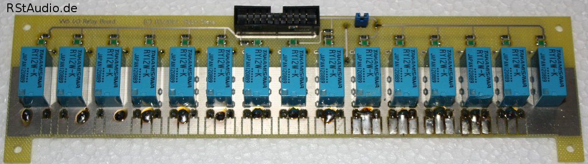
Relays Board of the Inputs and Outputs
For the control of the relay boards an I2C bus from the Control Module is used. This avoids the disturbance of digital signals into the analog circuits when nothing is switched. Additionally to the relay control a connector to control the XP-30 volume boards is placed on this board. Also a chip to measure the inner temperature of each individual Audio Module is integrated on that board.
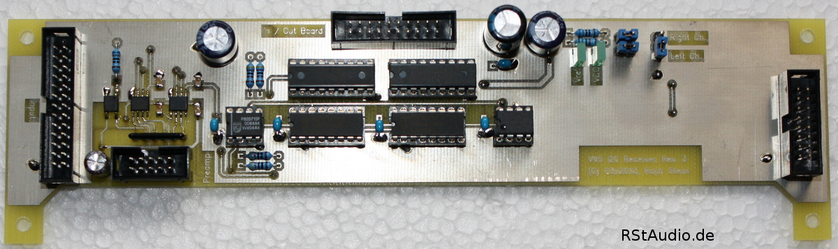
Control Board of the Inputs and Outputs
Assembly of the Cabinet
2012/11/28
For the cabinet I used 3 Slim Line 02/350 2U 10mm Silver (1NSL02350B) from HI-FI 2000. They are really very proper for the price and their design is acceptable. I took again a Datron M35 for the drill holes, milled edges and the inscriptions.
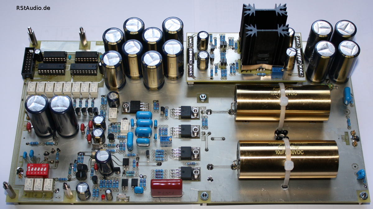
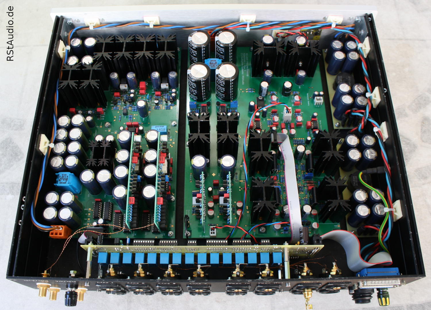
On the photo below you can see the installation of the electronic in the Control Unit. Direct centrical mounted at the front cover is the microcontroller board, both rotary pulse encoders are placed on the left and right side of the µC board and on the left side the power push button is mounted. On the bottom left side of the cabinet you find the board for the phase detection, above the line filter and the board with the DC filter and the power supply for the control system are mounted. In the middle of the cabinet both toroidal transformers for the audio power supplies are placed – as allways individual produced from RONDO Ringkerntransformatoren. Nearly the whole left side is used from the audio power supply board.
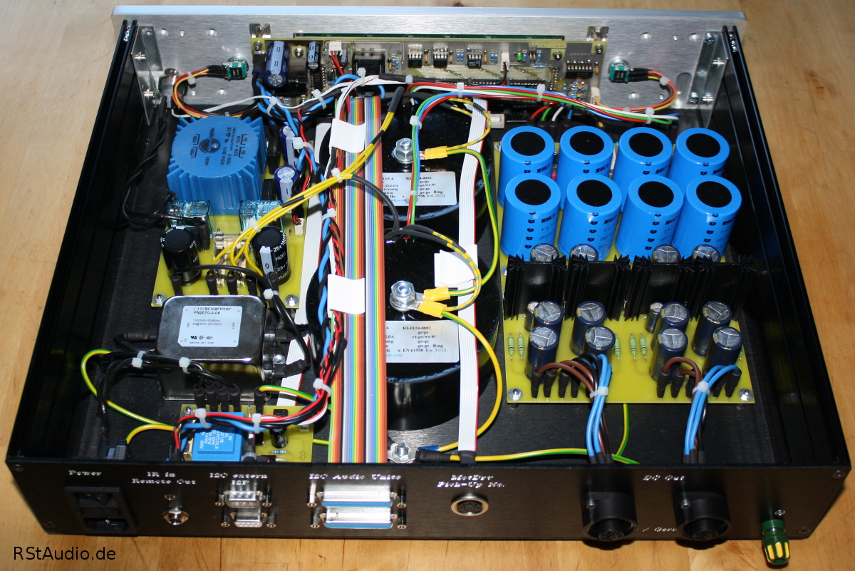
View at the Electronic of the Control Unit from the Rear Side
In both Audio Units I glued a 3mm thick heavy foil on the bottom and top plate to suppress resonances. The spacer to mount the PCB’s are mounted at the bottom plate and therefore I have to put openings in the foil for them. The cabinet feet are made from Sorbothane.
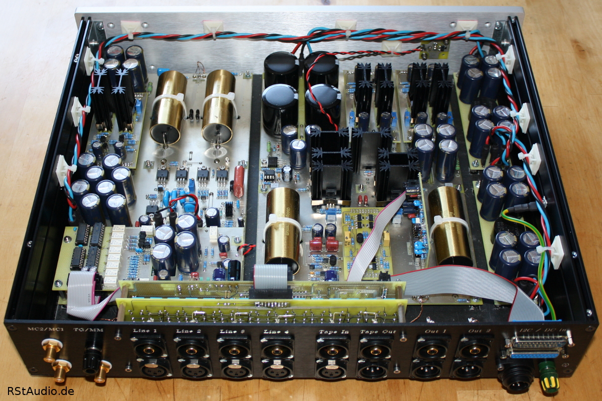
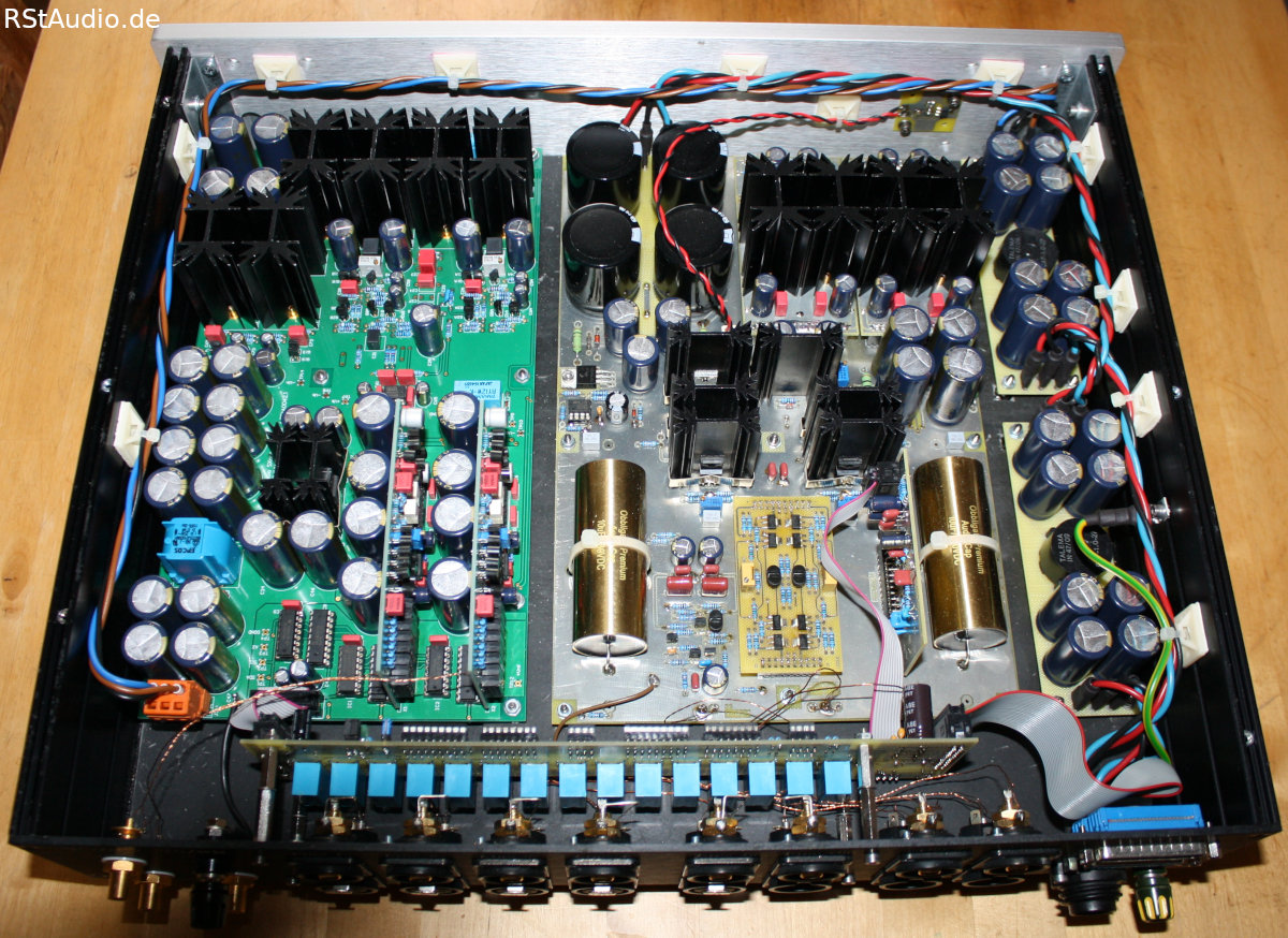
View at the Electronic of the Left Audio Unit from the Rear Side
The two PCB’s mounted at the back plane are the Relay Board to switch the input and output signals and above of it the Control Board which distributes the control signals. At the left hand side of the cabinet the XOno with it’s daugther boards is mounted and at the right side of it the XP-30 is placed. On the right side of the cabinet you find the two CLC filter for the XOno and XP-30.
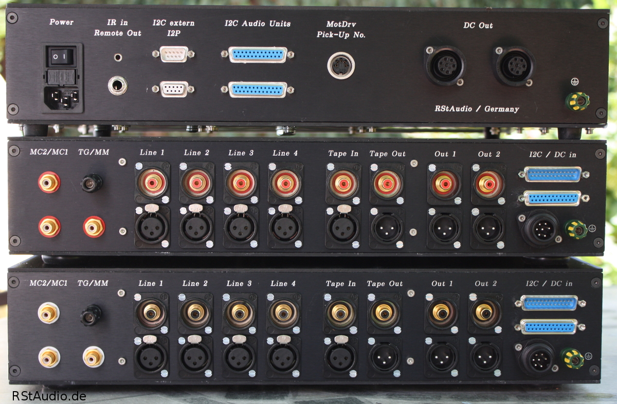
View at the Rear Side of the Complete VV5 Preamplifier
At the picture above you see all Units of the preamplifier standing above of each other with the view on the rear sides. On top the Control Unit is placed and beneath it you see the right and left Audio Unit. All informations about the inputs and outputs you find above.
Modifications and Improvements
2020/05/29
Of course even for a nearly perfect implementations is room for improvements and as a consequence I have done some modifications in the meantime.
Power Supply for the Audio Modules
I integrated Snubber networks which I have described here after the bridge rectifiers. Additionally I replaced the diodes with SiC Schottky types (Silicon Carbide).
Input and Output Relay Board
From the beginning on I don’t like the installation of the I/O relay board together with it’s control board. A problem with the communication between the microcontroller and the MUSES chips gave me the chance to build them new.
The following conditions are part of my personel specifications:
- Both boards combined on one PCB
- Optimization of the SPI communication between the microcontroller and the MUSES chips
- Direct connection of the audio signals to the relay pins
- not selected inputs have load resistors switched (not open)
Top Side of the I/O Board
Bottom Side of the I/O Board
Discrete Voltage Regulator
I also revised the two discrete voltage regulators for the XP-30 clone and the appropriated regulator for the XOno. I have made five changes:
- Integration of a low pass filter for the reference voltage of the regulator
- frequency dependent amplification of the regulator circuit
- optimization of the operation point for the regulator circuit
- fixed output voltage of each board
- use of bigger heat sinks by keeping the same board dimension as before
View on the XP-30 Board with the new Voltage Regulator Boards installed
DPV1 Phono Preamplifier
After more than a decade listening via the XOno phono preamplifier I decided to build my own discrete phono preamplifier. A description of this preamplifier can be found here. I designed the board of the DPV1 to replace the XOno board in the VV5 without any mechanical modifications.
VV5 Preamplifier with DPV1 Phono Preamplifier
XC-22A Preamplifier Board
I have lived 7 years extremely satisfied with the replica of the XP-30 preamp board. For me the XP-30 was and is one of the best available preamplifiers. But as the saying goes: The better is the enemy of the good. The only point of criticism that this preamplifier might have to put up with is the AC coupling in the signal path. Basically I have nothing against such a circuit technology, but my developments of the last years have shown me that a DC-coupled stage with servo controller has advantages. Therefore I exchanged the XP-30 board in May 2020 with the XC-22A board.
VV5 Preamplifier with DPV1 Phono Stage (left) and XC-22A Preamplifier (right)