!!! Printed Circuit Boards Available !!!
Table of Contents
- Introduction
- Description of the XOno Hardware
- Microcontroller Board
- Power Supply
- Installation in an Enclosure
- Audiophile Review
- FAQ
- Printed Circuit Boards
Introduction
May 1, 2019
Unfortunately, Toshiba’s exceptional 2SK170 JFETs—also known as “Gold Dust”—are running out. The supplier I’ve always recommended can no longer offer them. This means it will be difficult, if not impossible, to build an original XOno.
At the end of 2018, I decided to build an MC preamplifier based on the XOno topology using Toshiba’s 2SK2145 JFETs as a plug-in card for my DPV1 phono preamplifier. It was intended to serve as a test setup for a new XOno design. In early 2019, I successfully put this plug-in card into operation, so nothing stood in the way of redesigning the XOno.
However, the circuit should still be based as closely as possible on the original XOno design, albeit with some sensible improvements drawn from the Pass Labs XP-15 and my own many years of experience. I have included the following points in my personal specifications:
- Optional configuration with 2SK170 / LSK170 or 2SK2145.
- Reference voltage source instead of a simple LED for the RIAA amplifier’s current sources.
- Modernized design of the inverter (XP-15).
- Optional configuration with DIP switches or relays.
- Optional AC or DC coupling at the outputs of the RIAA stage and the inverter.
- DC supply voltage input with CLC filter.
- Discrete voltage regulation with modified Jung regulator.
- Add-on board with additional equalization curves (Columbia, Decca, EMI & Teldec).
- Microcontroller circuit board for relay operation.
- Predominant use of through-hole components.
Description of the XOno Hardware
August 11, 2020
The goal of the design was to develop an XOno using components currently available on the market. The 2SK170 (“Gold Dust”) transistors used in the original can therefore be replaced with currently available 2SK2145 transistors. However, the 2SK2145 is a dual JFET in a 5-pin SOT package. The design of this phono preamp is largely based on the original, though it incorporates several useful modifications and improvements drawn from the XP-15 design and my own many years of experience.
MC Input Stage
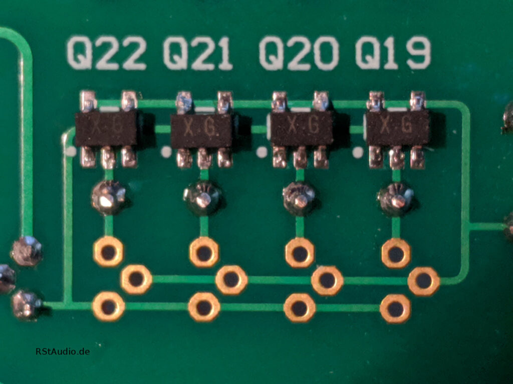
The circuit topology of the MC stage corresponds to that of the XOno. I have simply moved the gain adjustment to the output of this stage, as is the case with the XP-15 design. This seemed more sensible to me than directly adjusting the gain factor, as is done in the original. Both stages of the MC pre-preamp are based on the JFETs mentioned above. The stage can be built using five 2SK170s or an equivalent number of 2SK2145s. When using the dual JFETs, this results in a significant reduction in noise due to the doubled number of transistors connected in parallel. However, the operating points must be adjusted to account for the different number of transistors, meaning different resistor values are required.
At the input of the MC stage, there are eight switchable resistors for matching the cartridge being used. In the original XOno, these resistors are selected via a DIP switch on the circuit board. Of course, you can set it up the same way with this circuit board. However, if you prefer a more convenient solution, you can also solder relays onto the circuit board. In combination with the optional microcontroller board, the resistors can then be selected via the display and a rotary encoder.
The three gain factors of the MC stage are also set either via a DIP switch on the circuit board or using relays controlled by a microcontroller.
MM Phono Preamplifier
In this stage, either the 2SK170BL or 2SK2145BL transistors can be used for the input differential amplifier. No adjustments to other components are required. Additionally, there is a significant improvement in the reference voltage of the current sources compared to the original XOno. Instead of a red LED, I use a TL431 reference voltage diode here. As a result, the operating point is no longer dependent on the batch of the component used. The TL431 has a specified output voltage of 2.5V in the circuit topology used here. Otherwise, this amplifier corresponds to the original XOno design.
Three capacitors can be connected to the input of the MM amplifier. The same applies here as mentioned above: You can either use DIP switches or relays in conjunction with the optional microcontroller board.
Inverter
The inverter is located at the output of the MM stage and generates the inverted signal to produce a balanced output signal. I decided to use a more modern design from Pass Labs here, as the original IRFD9110s get extremely hot. The current inverter runs much cooler and sounds at least as good.
Servo Controller
In the original XOno, the MM amplifier and the inverter are AC-coupled. There are 10μF film capacitors at the output of both stages and at the input of the inverter. This XOno can also be built to match the original. Space is provided for the large film capacitors.
However, if you install the two servo controllers, you can do without these coupling capacitors. This ensures that the outputs of the stages are electronically kept free of DC voltage. I first used this circuit design with great success in my DPV1.
Voltage Regulator
In the original design, the XOno circuit board receives its DC voltages from an external power supply housed in a separate enclosure. My designs also incorporated this separation (see below). The unregulated DC voltages are stepped down to the required operating voltages on the XOno board. Pass Labs used lofted 15V voltage regulators (7815 and 7915) to regulate the ±30V operating voltage. In my old XOno, I used adjustable voltage regulators (LM317 and LM337) in this section.
In the current version, I use modified Jung regulators. I first used them in my DHA and am thrilled with their audiophile and regulation performance. On the circuit board in front of these regulators, I also use CLC filtering with a current-compensated dual choke and a total capacitance of 60,000μF.
EQ Board
Older, interesting classical recordings often don’t sound particularly good when played through a modern phono preamp. However, this isn’t due to the quality of the preamp, but solely to the incorrect equalization curve. Recordings from the 1960s or earlier were often not cut using the RIAA curve (for example, Deutsche Grammophon).
During the development of the XOno, I was asked to include additional equalization curves. However, since not everyone is interested in this — myself included — I decided to offer an optional expansion board. This board adds four additional equalization curves (Columbia, Decca, EMI, and Teldec) to the XOno. This should make it possible to correctly equalize the majority of these recordings.
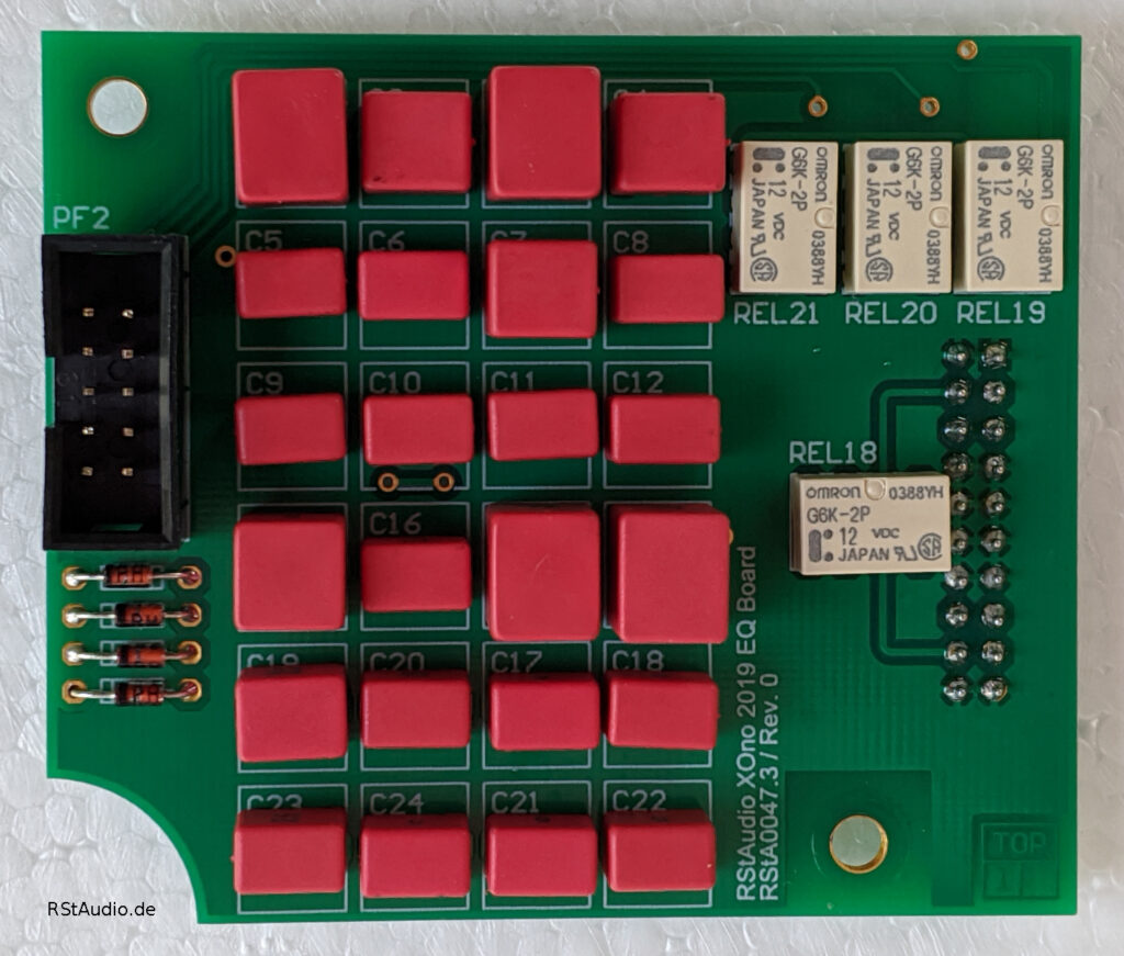
The photo above shows the EQ board for a single channel. The required SMD resistors (1206) are mounted on the bottom side of the board. To achieve the most accurate frequency response curve possible, all capacitors were measured.
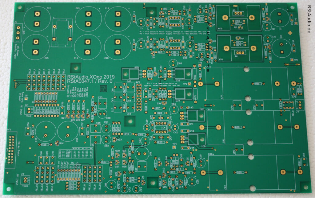
Photos of assembled XOno Boards
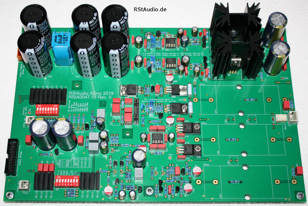
The photo below shows a fully assembled XOno board. This is the version with capacitor coupling, without a relay or EQ board — in other words, the classic XOno configuration. For the coupling capacitors, I used Aeon capacitors that I still had in stock. Similar capacitors were also used in the original XOno.
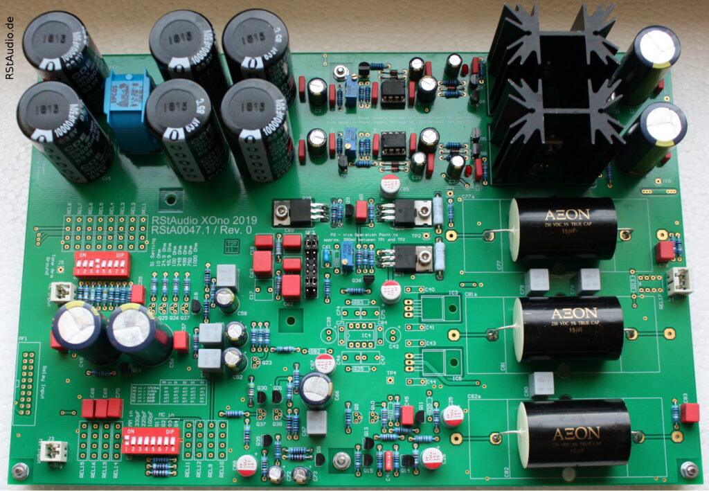
The next picture shows the version with a 2SK2145, servo controller, and relay, but without the EQ board.
Microcontroller Board
August 10, 2022
As mentioned above, a microcontroller board is available as an option for controlling the relays on the XOno board. The system is operated via a display with two rows and 20 columns, as well as a rotary encoder.
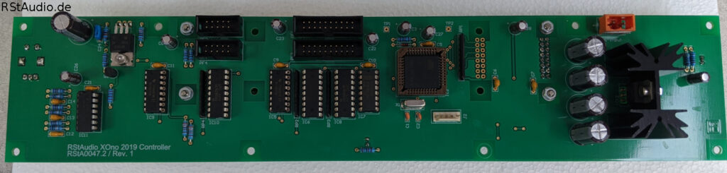
I use an OLED display from Display Visions. Two models can be installed on the board: the EA W202 XLG with 5.5 mm character height and the EA W202 XDLG with 9.66 mm character height. I prefer the larger display because it’s easy to read even from a slightly greater distance. Unfortunately, it’s no longer in production, so you have to make do with the smaller display.
The board uses a Microchip AT89C51ED2. Of course, I provide a controller board along with a pre-programmed microcontroller. However, there is also a connector to which you can connect a programming interface. So if you want to write your own software for the XOno, you certainly have the option to do so. I use only open-source software: SDCC and Flip.
The controller board features a built-in IR receiver. This allows the XOno to be fully controlled via a remote control.
Power Supply
March 25, 2020
An audio preamplifier — and especially a phono preamplifier — is particularly dependent on the quality of the power supply used. Over the years, I have gained a great deal of experience in this field, and my circuits have become increasingly complex, but also increasingly better. The RStAudio XOno 2019 features a power supply into which I have incorporated all the insights I have gained to date. I have already discussed the final section of the power supply, which is located on the XOno circuit board itself, above. Here, I will focus on the generation of the unregulated DC voltages.
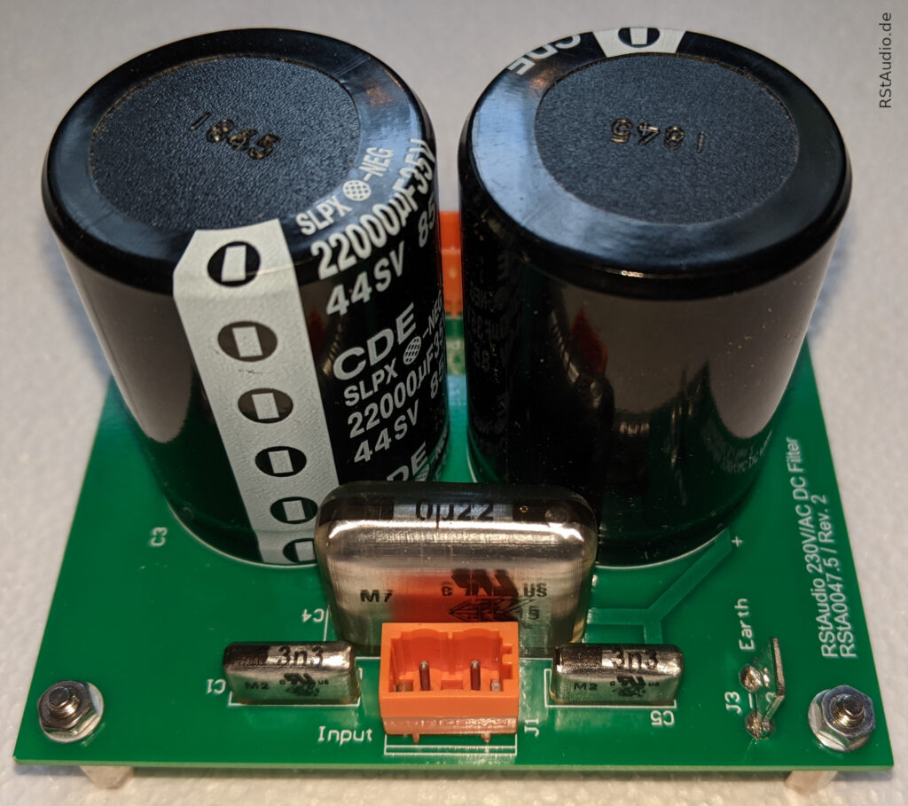
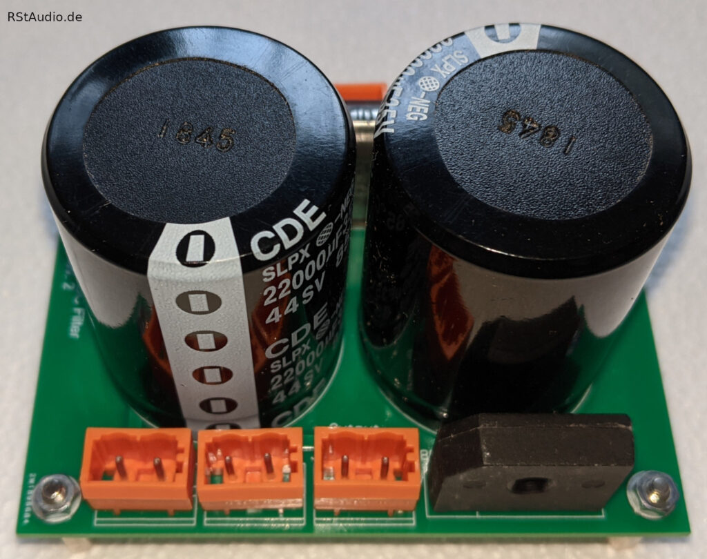
230V/AC DC Filter
Nowadays, disturbances in the 230V/AC mains supply are becoming increasingly common. It is therefore essential that these disturbances do not affect the DC power supply to the audio circuits. As a first line of defense, I have installed a power jack with an integrated filter from Schurter in all of my power supplies. This is followed by another filter with Wima X2 and Y2 capacitors, followed by a DC filter. This ensures that any DC components in the 230V/AC supply do not drive the transformer into saturation. There is sufficient space for larger electrolytic capacitors, as the rule of thumb applies: For every 100 VA, the DC filter requires 10,000μF.
Unregulated Power Supply for the Audio Circuits
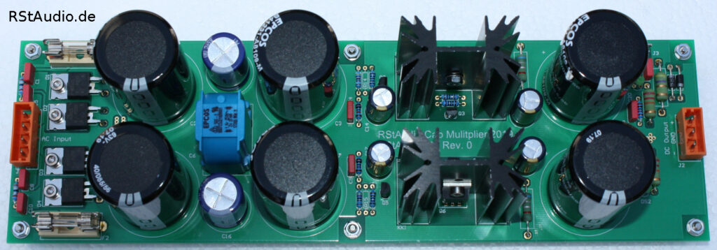
This circuit board is used to generate the unregulated, balanced DC voltage for an audio channel. As can be seen in the photo below, this is not the typical circuit consisting solely of a rectifier and charging capacitors.
The input, located at the left of the photo, is connected to two secondary windings of the transformer. Immediately following this are two snubber networks that significantly dampen the oscillatory tendencies of the resonant circuit, the inductance of the transformer and the reverse-bias capacitance of the diodes. Next is the bridge rectifier with discrete ultra-fast soft-recovery diodes. The next section of the circuit consists of a CLC filter with four 10,000μF capacitors and a current-compensated dual choke. This is followed by a capacitance multiplier, which removes any residual AC voltage components (ripple) from the DC voltage. The ground is connected to earth via a diode-resistor network. An extremely high-quality, though still unregulated, DC voltage is available at the output.
The output voltage naturally depends on the transformer’s turns ratio as well as on the AC voltage currently available at the outlet (230V/AC ±10%).
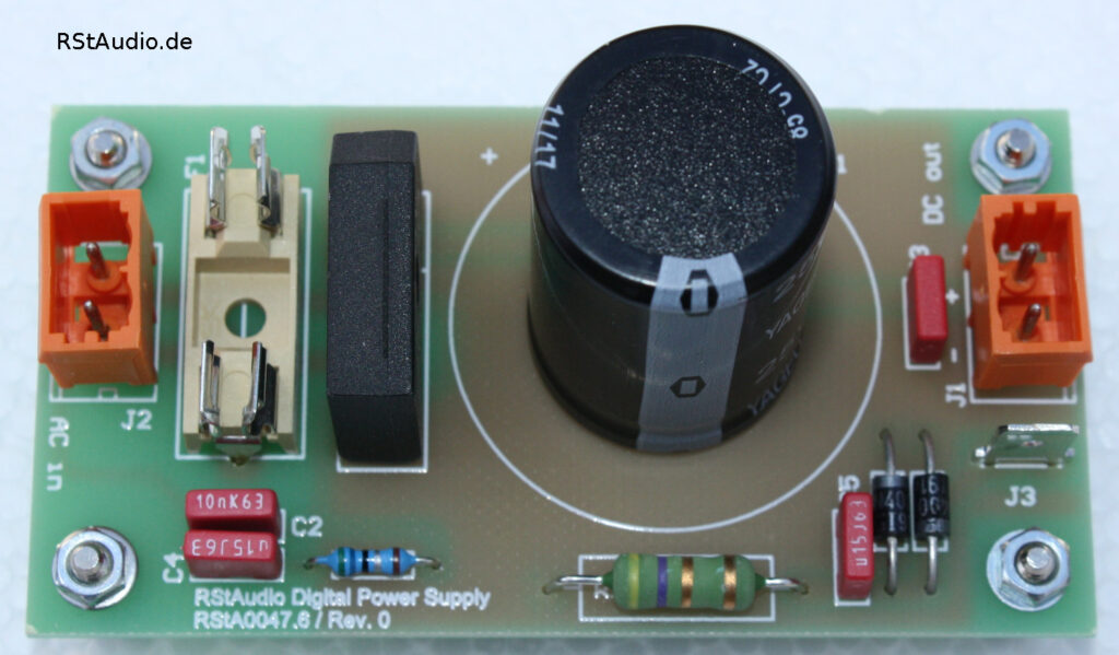
Unregulated Power Supply for the Digital Circuits
The power supply for the digital circuitry — and thus ultimately for the controller — is rather modest in design. Although it does include a snubber network and a ground connection, the power supply otherwise consists of a classic, unregulated setup comprising a rectifier and a charging capacitor. Even though the capacitor is very large. Since the controller has no direct connection to the audio circuits, this power supply is more than sufficient.
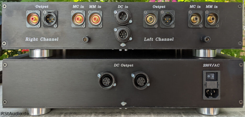
Installation in an Enclosure
August 14, 2023
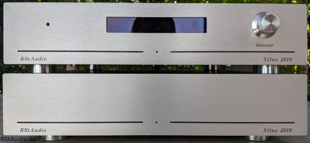
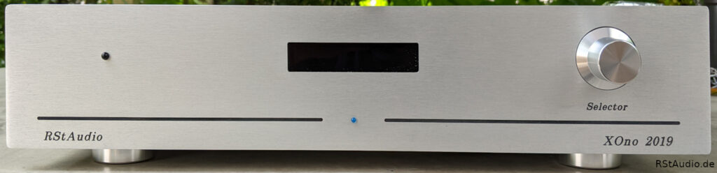
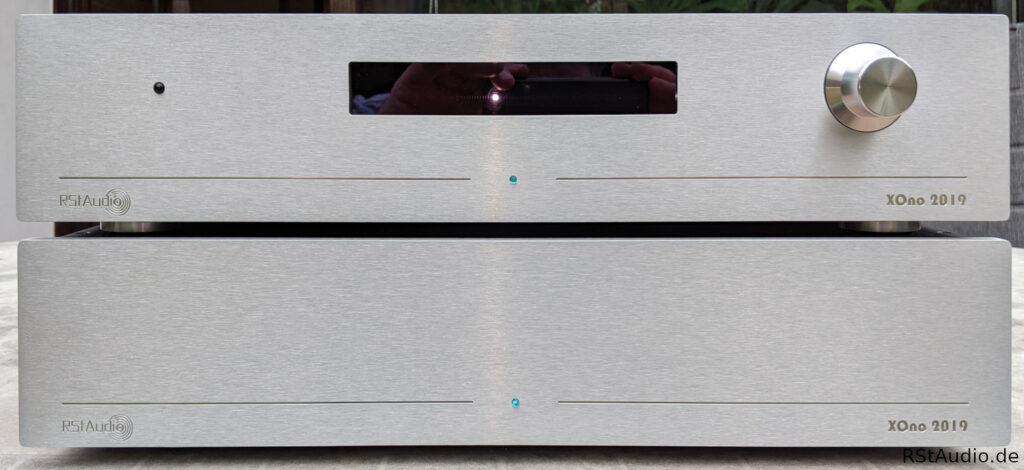
As usual, I bought the enclosures in Italy. The photo at the top of the page shows the front view. The front panel’s very successful design is the work of my friend Guido. The display is clearly visible in the center, and below it is the LED that indicates the operating voltage. The rotary encoder is positioned on the right side, with the IR receiver to its left. The power LED is useful because the display can be dimmed during operation.
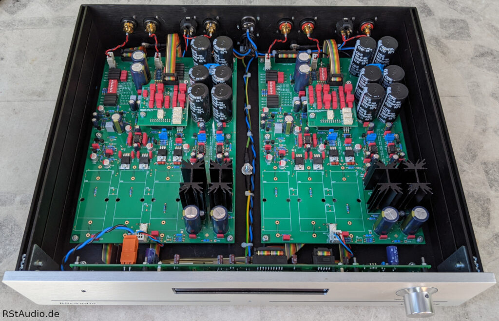
The photo above shows the RStAudio XOno 2019 audio chassis with the cover open. It is fully equipped, including relays, a controller, and EQ boards. It uses 2SK2145 JFETs. Additionally, this is the version with DC coupling and servo controls.
The front panel of the power supply has a very simple design. Since the RStAudio XOno 2019 is intended for continuous operation, the power switch is located on the back. The front panel features only an LED that indicates the operating voltage.
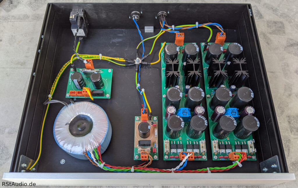
The electronic components of the power supply are clearly visible in the photo above. At the back left, you can see the power jack with the switch, fuses, and filter. The DC filter is located in front of this, and the toroidal transformer sits behind the front panel. I chose a single transformer with separate windings for the left and right channels. Even the best phono cartridges only achieve a channel separation of about 35dB, a value that the power supply easily surpasses.
On the right side are the circuit boards for generating the unregulated operating voltages. On the far right are the two audio power supplies, and further in is the simple power supply for the digital electronics.
The central grounding point is clearly visible. All grounding wires are connected directly to this point. You can also clearly see how I achieved isolation of the individual signal groups (230V/AC, secondary AC and DC) in the wiring through this installation.
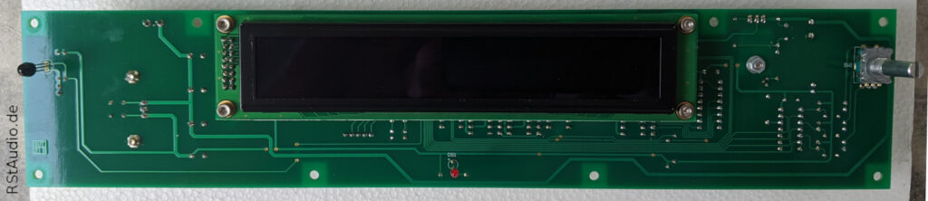
The following photo shows the front of the audio enclosure with the small EA W202 XLG display from Display Visions.
On Meinolf Stute’s website, you can view a very nice and detailed build guide. He has documented the progress of his project with a wealth of fantastic photos. This gives you a very good sense of the project. By the way, his RStAudio XOno 2019 comes fully equipped.
More photos can be found in the photo gallery of the assembled XOno devices. The builders have kindly provided me with their photos.
In early 2021, I built an RStAudio XOno 2019 for my friend Guido. What makes this unit special are the front panels. Guido converted my logo into CNC milling data and had them milled by a metalworker friend of his. Incidentally, this is the same supplier used by clearaudio. The result is a beautiful RStAudio XOno 2019. The lettering was intentionally left unblacked, as he simply prefers it that way.
Audiophile Review
July 22, 2022 / Ralph Stens
I’ve been listening to music with the prototype for some time now. First with the version featuring 2SK2145 transistors and capacitor coupling, and then with servo controls. The XOno with the 2SK2145s is, as I had already experienced during the test setup of the MC stage for my DPV1, extremely low-noise. Otherwise, the version with capacitor coupling is a perfectly normal XOno —and I mean that as a huge compliment! However, this phono preamp really shines when you use the servo controllers. For me, this is the best XOno I’ve ever heard.
So my recommendation is:
XOno with 2SK2145 and Servo Controllers
In this solution, it must be ensured that the following input to which the RStAudio XOno 2019 is to be connected does not produce any DC voltage. If this is the case, a capacitor coupling must be used. However, the presence of such DC voltage would constitute a serious design flaw in the subsequent device.
You can read more reviews of the RStAudio XOno 2019 here.
FAQ
September 15, 2020
Customers who purchase the RStAudio XOno 2019 circuit boards will receive access to a secure FAQ page. I will send you the access code.
Printed Circuit Boards
August 26, 2020
I am making the complete set of circuit boards for this project available to DIY enthusiasts. Upon receiving an email request, I will send a detailed list with all the necessary information.
If you are interested in printed circuit boards, please use the contact form below.
Please make sure to enter your email address correctly. Otherwise, responses to your inquiries simply cannot be delivered. You can rest assured that I will respond to every inquiry. If you do not receive a reply from me, please check your spam folder as well.
Unfortunately, the contact form isn’t working for some users. In that case, please send me an email at
info[at]rstaudio[dot]de
Please replace the text in the square brackets as appropriate (SPAM protection).