Table of Contents
- Introduction
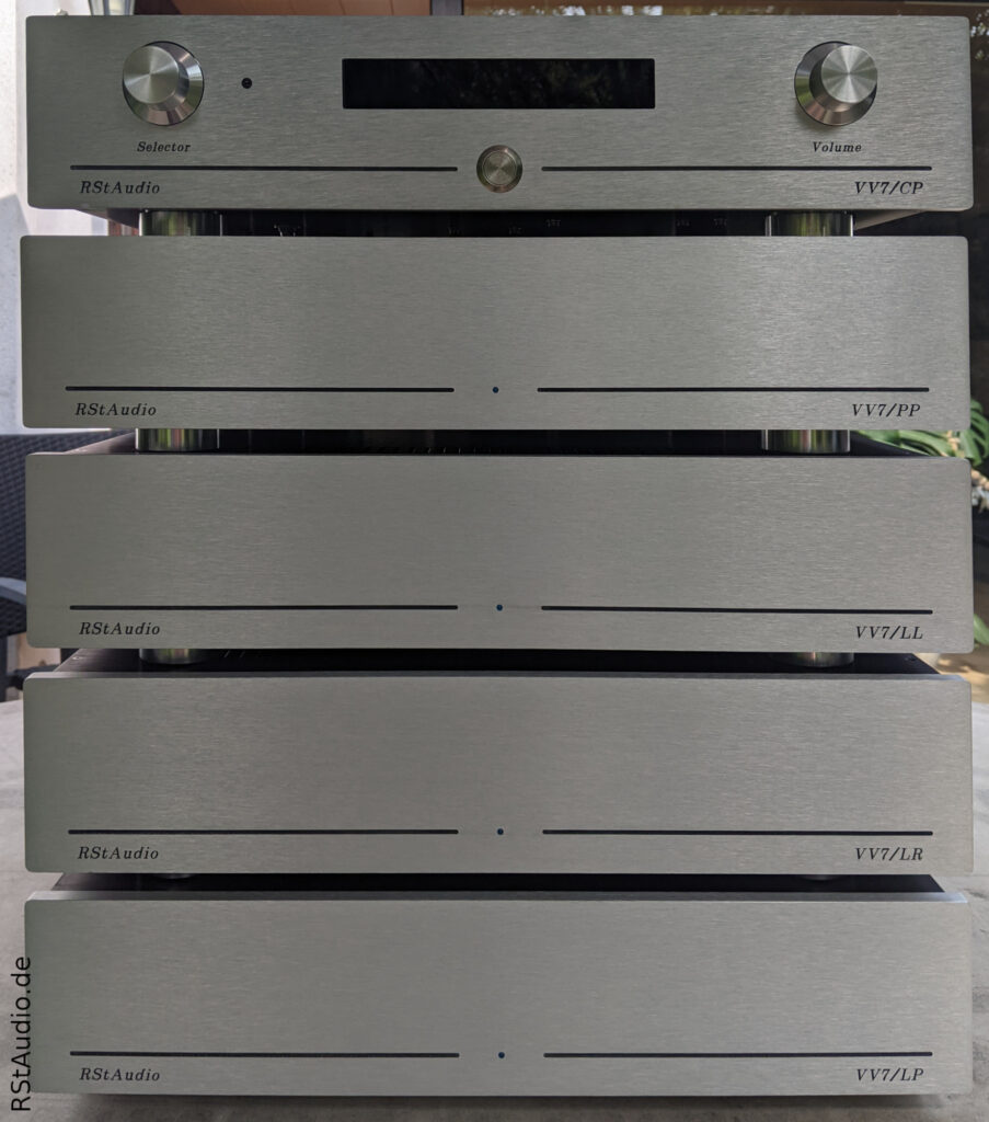
- DPV1R2 / DPV1R3a Phono Preamplifier (VV7/PP)
- Line Preamplifier (VV7/LL & VV7/LR)
- Controller & DPV1R2 Power Supply (VV7/CP)
- Power Supply for Line Preamplifiers (VV7/LP)
- Audiophile Review
Introduction
December 9, 2021
In 2016–2017, I built a 12-channel preamplifier for my friend Heiner. At that time, he had already been using a system topology for many years that I have also been using since early 2021. At the heart of both our systems is a multichannel A/D & D/A converter and a PC running convolution software. With this type of setup, it makes sense to place the volume control — and thus the actual preamp — after the converter. The analog sources are connected to the converter, while the digital sources feed their signal directly into the convolution PC. The sources are then switched directly on the PC, usually using a tablet. This topology prevents the A/D converters from being under-driven by the analog sources at low volumes, which would result in a loss of resolution. It also eliminates the need for additional D/A and A/D conversion for the digital sources.
Unlike the VV6, however, my preamplifier was to be equipped with different amplifier stages. The XC-22A line stage continues to handle signal processing for the Quads. In the bass and treble ranges, this stage features an OPA1632 at its core. All in all, it is a 2/10-channel preamplifier with five line stages per audio channel.
- 2x XC-22A for the Stacked Quads
- 3x OPA1632 Line preamp for treble and bass (Mundorf Air Motion Transformer, RiPol, …)
In addition, there is a phono preamp based on my DPV1.
All units are controlled by a single microcontroller. The controller board is housed in a single enclosure along with the unregulated power supply for the phono modules. The line stages have their own power supply. The entire preamplifier is enclosed in five separate housings.
I’ve had a GW Instek LCR-6020 at my disposal for some time now (thanks a lot, Guido!). Using this wonderful measuring instrument, I’ve calibrated the passive components that affect the gain or the amplitude response (frequency and/or phase) with an accuracy of ±0.1% of the nominal value. This is an extremely labor-intensive process that would never be commercially viable. As a result, deviations between the channels should no longer be measurable, especially since I also match the semiconductors to each other.
I have a large stock of 2SK170/2SJ74 transistors, all of which I measured years ago using a Peak Atlas DCA75 Pro. In the meantime, however, I learned that the JFET measurement results from this device are not reliable in the final circuit. Simply put, the current flowing during the measurement is too low. That is why I am re-measuring all JFETs using the JFET measurement setup from the XOno 2019. Of course, I also used my much higher-quality Agilent 34401A benchtop multimeter for this.
With every project, I learn something new, so my devices keep getting better and better, both technically and in terms of their mechanical design. Thanks to the front panel design by my friend Guido, the aesthetics have also improved significantly. It’s my biggest DIY audio project to date.
The VV7 has been running in my system since May 21, 2022, and has replaced the VV5.2.
DPV1R2 / DPV1R3a Phono Preamplifier (VV7/PP)
November 29, 2024
The DPV1 phono preamp has been running to my complete satisfaction since April 2018. Naturally, I wanted to incorporate this preamp into the VV7 design. However, after years of use, I had a few ideas about what could be improved, which is why I made some changes to the DPV1’s design.
Most of these changes are largely cosmetic and do not affect the audiophile performance of this phono preamp. Only the regulated power supply has been extensively redesigned. Instead of the discrete voltage regulators from Pass Labs, I used the modified Jung regulator, which has become my preferred choice. Consequently, I named this phono preamp the DPV1R2 — where R2, of course, stands for Revision 2.
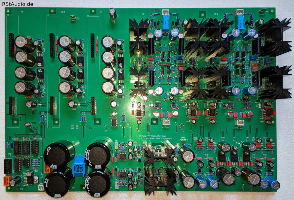
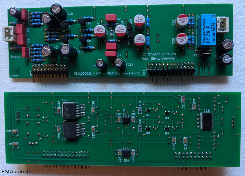
The DPV1R2 consists of three or four functional blocks for signal processing — depending on how you count them. The first functional block at the input is an MC pre-preamp. The gain is linear. Since this functional block is present twice, there are three or four blocks. A relay directly at the output of these two blocks switches between them, ensuring that only three blocks are ever in the active signal path. The subsequent second functional block is another amplifier stage with a non-linear transfer characteristic. RIAA equalization takes place here. This functional block provides the positive output signal. The third block is an inverter that generates the negative output signal for balanced transfer technology. Its input is connected to the output of the RIAA amplifier. This phono preamp is designed exclusively for MC cartridges. For an MM system, the gain in the MC preamp would have to be significantly reduced. Personally, however, I have owned only MC systems for more than 40 years, so this is not a drawback for me.
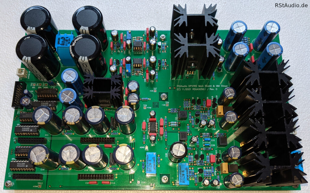
The digital relay control circuit is located at the front left of the DPV1R2 board. It consists of I2C bus port modules followed by open-collector Darlington drivers. The separation of the two ground planes (analog and digital) is clearly visible.
The slots for the two MC pre-preamps are also located at the front left. Directly behind each slot are the additional voltage regulators (post-regulators) for the MC stages. They are connected downstream of the main regulator and supply the MC stages with approximately ±24V.
The inverter is located on the right front side. It provides the negative signal of the balanced output voltage. Behind it is the MM amplifier with active 318μs or 3180μs RIAA equalization. Additionally, the 7950μs time constant can be switched. Both amplifiers are implemented as discrete operational amplifiers. The output stages have a relatively high quiescent current, which explains the very large heat sinks. Furthermore, they are driven by additional constant-current sources with a crossover-displacement circuit. The 75μs equalization is passive and is located between the MC pre-preamp and the MM amplifier. The 8-pin IC in the center of the photo is a dual op-amp. It forms the two servo controllers for both DC-coupled discrete operational amplifiers.
The power supply occupies the entire rear section of the circuit board. The unregulated operating voltage is connected on the left side. This is followed by a CLC stage with four 10,000μF capacitors and a current-compensated dual choke. Next comes the modified Jung regulator. Finally, there is a CRC filter at the output.
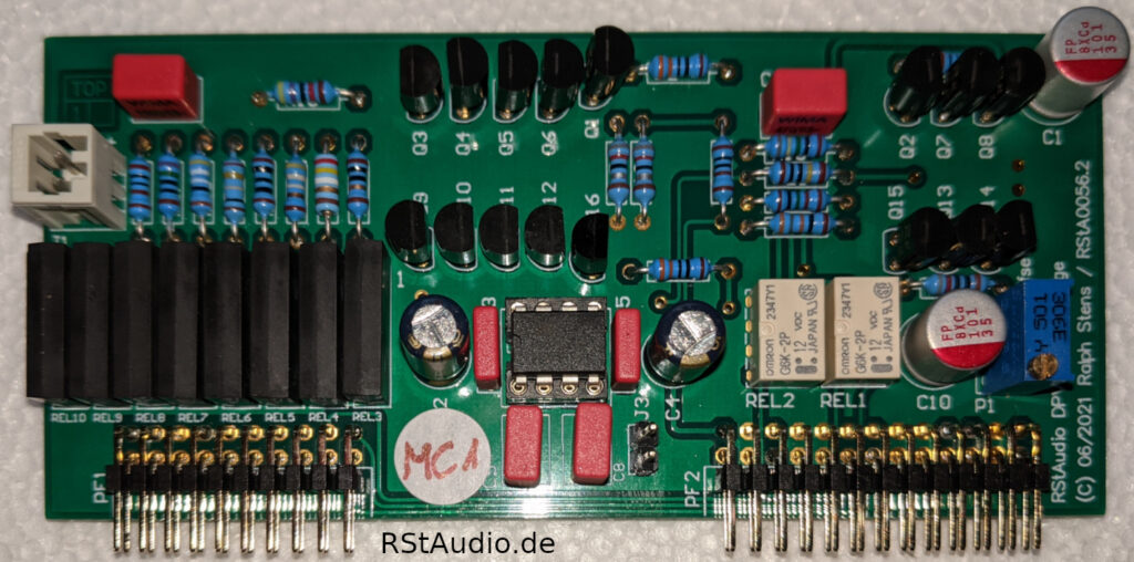
The MC preamplifier has a three-stage design. With the exception of the two cascode transistors in the input stage, only n-channel and p-channel JFETs are used (7x 2SK170BL and 7x 2SJ74BL). Eight resistors can be selected at the input, which can of course also be combined. This theoretically results in 256 possible combinations. However, since many values do not differ significantly from one another, I have only programmed the useful resistors into the software. In addition, four different gain factors can be selected. The board is DC-coupled throughout and is kept free of DC voltage at the output by a servo controller — the operational amplifier shown in the image above.
As you can see in the photo above, the case is quite full due to the two audio boards. The board located behind the front panel is part of the DPV1R2’s digital section and handles the distribution of control signals to the two audio boards. The digital operating voltage is also regulated by a standard 5V regulator. The front panel LED is directly soldered onto the board as well. It is powered by an adjustable current source, allowing me to match its brightness to the other LEDs on the VV7. This board also houses a chip for measuring the internal temperature of the VV7/PP.
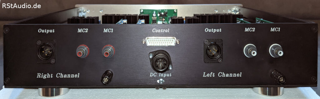
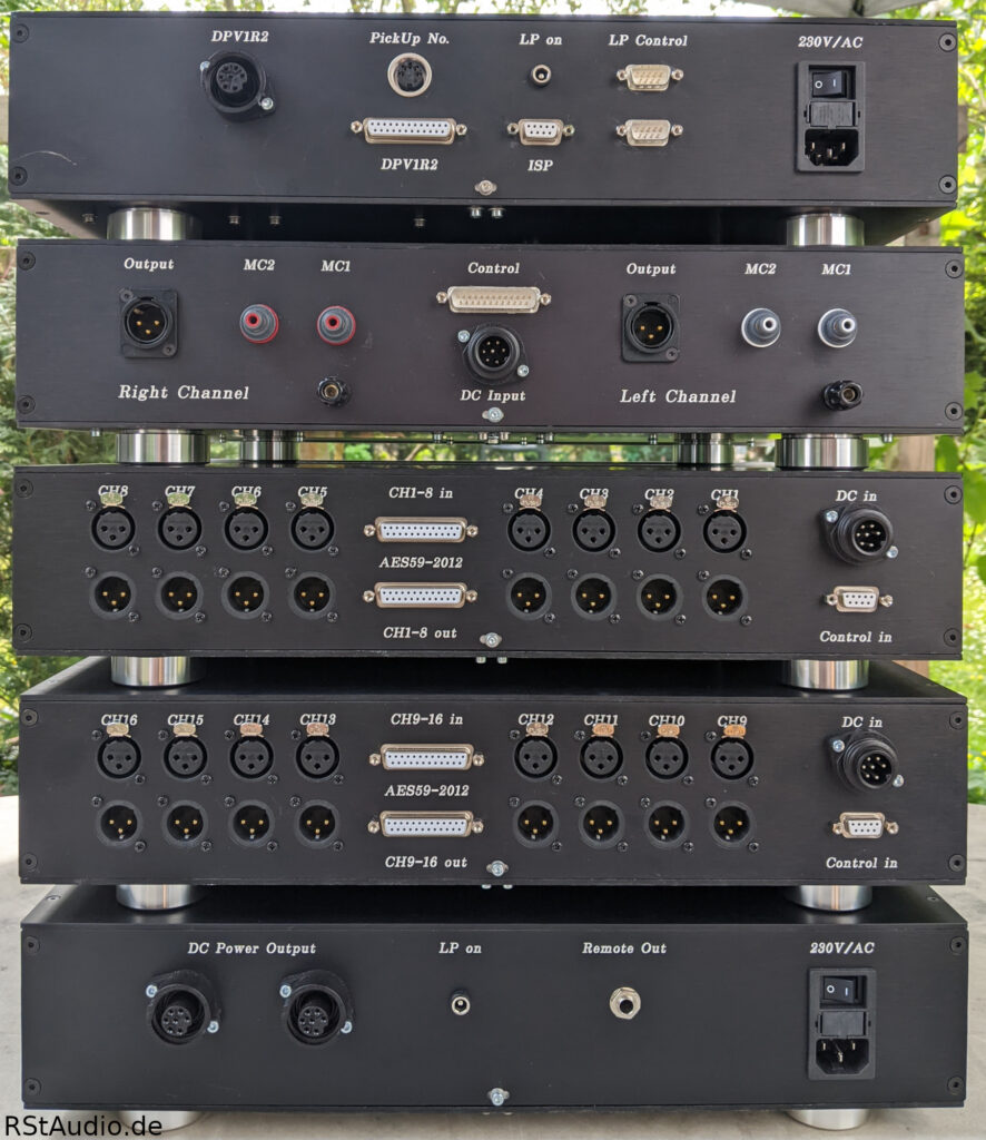
The connectors for the DC power supply and digital control are located in the center of the rear panel. To the left and right of these are the audio connectors. Since I always position the two channels from a front-view perspective, the connectors appear reversed when viewed from the rear — that is, the right channel is on the left side and vice versa. The RCA jacks for the MC inputs are from WBT, and the XLR jacks for the outputs are from Neutrik.
Update on DPV1R3a in Fall 2024
Unfortunately, I kept experiencing thermal issues with the DPV1R2 during the height of summer. These problems originated at the MC input and were caused by the very compact design. Some components (resistors) could no longer dissipate the heat effectively, causing them to literally burn out. This significantly increased the noise from the phono preamplifier. I had to replace the resistors every time.
It happened again during a demonstration in the summer of 2024. Only this time, I decided to tackle the problem head-on.
The main cause of the thermal issue was the lack of space, which necessitated a compact design around the two MC modules. Since the size of the circuit board could not be changed, I had to delve into circuit design.
I built the DPV1 just for myself, and I have no plans to ever change that. The large amount of gold dust required (2SK170 & 2SJ74) alone makes that impossible.
I choose my cartridges very carefully and keep them for my entire life. The two cartridges connected to the DPV1 are among the best the market has to offer. It’s highly unlikely that I’ll ever replace them. I know the technical specifications (input impedance and capacitance, as well as gain) very well. For this reason, the relays in the DPV1R2 input stages have hardly ever been switched.
It therefore makes sense to eliminate the relays and their control circuitry. In the DPV1R3a, the two MC inputs are equipped with fixed input resistors and gain factors. These are precisely matched to the requirements of the respective pickup.
This frees up so much space on the circuit board that I no longer need any add-on boards. The two MC stages can be mounted directly on the circuit board. This allows the waste heat to escape upward, eliminating any heat buildup. I was also able to move the large capacitors of the voltage regulators slightly to the side. This created additional space right next to the MC stages.
I redesigned the circuit board layout. From the very beginning, I deliberately chose a 4-layer PCB. This resulted in significantly better trace routing and gave me the freedom to dedicate an entire layer to a ground plane. It took two layouts before I was satisfied with the result — hence the “a” at the end of the name.
Line Preamplifier (VV7/LL & VV7/LR)
May 2, 2022
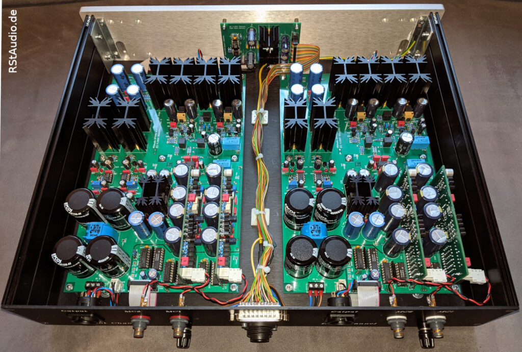
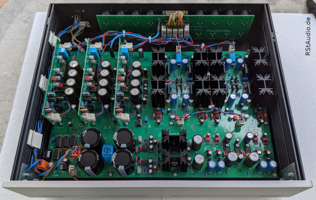
As I mentioned above, this preamplifier is designed as a 2/10-channel system. Each audio channel consists of the two XC-22A line stages, the Jung regulator, three slots for additional line stages, and a digital control unit for control via the microcontroller. It is the largest circuit board I have developed for one of my DIY projects to date — alongside the active absorber.
As always, I’m using the custom-built enclosures from Italy. Since the line-stage boards require so many components, I had to use a separate enclosure for each one. But I wasn’t willing to compromise under any circumstances.
The photo above shows one channel of the preamplifier. The digital interface is located at the bottom left. To the right of it is the ±32V operating voltage regulator, the modified Jung regulator. On the right side are the voltage regulators for the two MUSES72320s and the servo regulators (±15V and +5V). At the top left, you can see the three slots for the OPA1632 boards. To the right of each are the post-regulators, which generate the required ±15V from the ±32V. At the top left are the two XC-22A line stages. The PCB is populated on both sides; all SMD components are located on the bottom side.
XC-22A Preamplifier
July 9, 2021
This line preamp, designed by my friend Hans, surpasses anything I’ve heard so far — both commercially available and DIY models! However, the effort involved is considerable, and it’s really not necessary, for example, as a preamp for the bass range. When designing the VV7, I decided to continue powering the ’57 Quads via XC-22A line stages. Consequently, there are two of these preamps per audio channel in the setup.
Volume control is, of course, once again handled by a MUSES72320 connected upstream of the respective line stage. Here, too, the chip’s ±15V operating voltage is derived from the ±32V supply using the extremely low-noise integrated voltage regulators TPS7A49 and TPS7A30 from Texas Instruments. This design has proven itself excellently in the VV5.2.
OPA1632 Preamplifier
March 19, 2022
I’ve used this balanced operational amplifier in a wide variety of signal-processing applications, including — with great success — in my friend Heiner’s 12-channel VV6 preamplifier. Rumor has it that the chip features a supersymmetrical design. In any case, this op-amp sounds absolutely stunning, which is why I decided to use it for the additional line preamps.
Naturally, the excellent MUSES72320 was also used for these boards. Unlike the VV6 design, however, I placed the OPA1632 after the MUSES. Since the balanced op-amp has two inverting inputs, a buffer must be used between the MUSES and the OPA1632 (keyword: loaded voltage divider). Otherwise, you would have to work with very high impedance around the op-amp, which would naturally have a negative effect on the stage’s noise. I opted for a JFET buffer using the BF862, a design with an extremely neutral sound.
Behind the OPA1632, I used two LME49600s, which are integrated into the op-amp’s negative feedback loop. This means that long signal lines to the power amplifiers are no longer a problem. In addition, a servo controller keeps the balanced output free of DC components.
I can disable the power supply to each individual expansion board using a jumper. This allows me to avoid the consumption of a few milliamps by hardware that is not needed in the current system topology.
Backplane
May 1, 2022
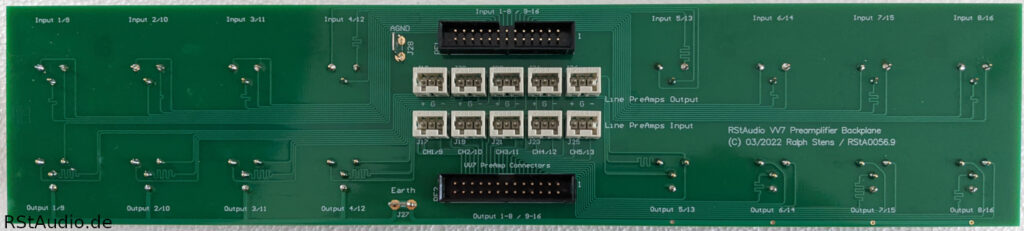
The two enclosures are also used to convert the 16 inputs and outputs of the Lynx Aurora(n) from the 25-pin AES59-2012 connectors (Tascam) — which are standard in studio equipment — to XLR. To do this, the connections from an LM-AIO8E card are routed into one of the two line preamp enclosures.
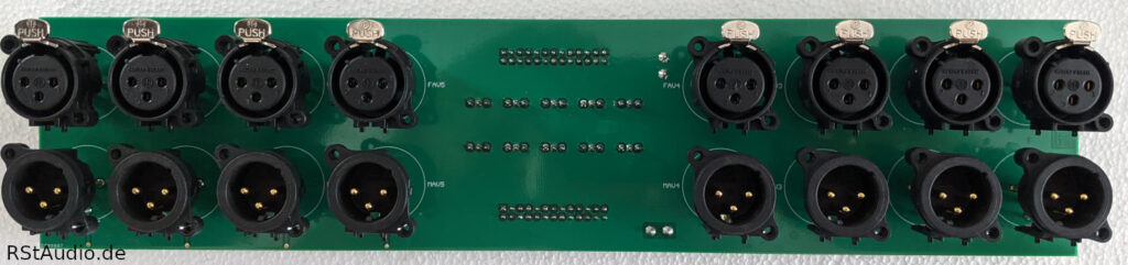
The eight XLR input jacks are directly connected to the corresponding Sub-D jacks. For the outputs, this is only the case for the last three XLR jacks on channels 6–8 and 14–16. The first five outputs are routed to five 3-pin Wago connectors, which are linked to the preamplifier inputs. The outputs of these preamplifiers are connected to the backplane via additional Wago connectors. These, in turn, are attached to the first five XLR output jacks (channels 1–5 and 9–13) on the circuit board.
So, on one end, my system is equipped with XLR connectors, while the connection between the Lynx and the preamp is made via Tascam jacks. For this, I use pre-made cables from Cordial.
The VV7’s Gain Concept
May 18, 2022
As described in the introduction, the VV7’s line stages are located behind the Lynx converter (D/A outputs). This means that the crossover generated by the convolution PC is also positioned in front of the line stages. This is why a multichannel preamplifier is necessary in this system topology. Currently, my crossover provides seven channels: 1 x mono subwoofer, 4 x quad, and 2 x Mundorf.
Since different speakers and power amplifiers do not necessarily produce the same volume level, active topologies require appropriate level matching. Fine-tuning of this level adjustment is performed in the Convolver and is defined via the target curve. For a more general initial setting, the preamp channels themselves are used.
The VV7 software allows you to set a custom volume correction for each line stage. The XC-22A preamplifiers — and thus, of course, the Quads — determine the base level. This means the channels for the subwoofer (RiPol) and the tweeters (Mundorf) must be matched to the Quads. As described, this can be achieved via the software and, if necessary, by adjusting the gain factor of the OPA1632 line stages. It also gives me the ability to balance the Quads against each other.
All of my power amplifiers operate with a gain of 26dB, while the VV7’s preamplifier modules operate with a gain of 6dB.
Enclosure Installation
May 8, 2022
As I’ve mentioned several times before, each of the two line-preamp boards is housed in its own enclosure. Given the size of the boards and the connectors required, no other solution is feasible. However, my priority isn’t a compact design; rather, it’s about bringing all my requirements and ideas to life.
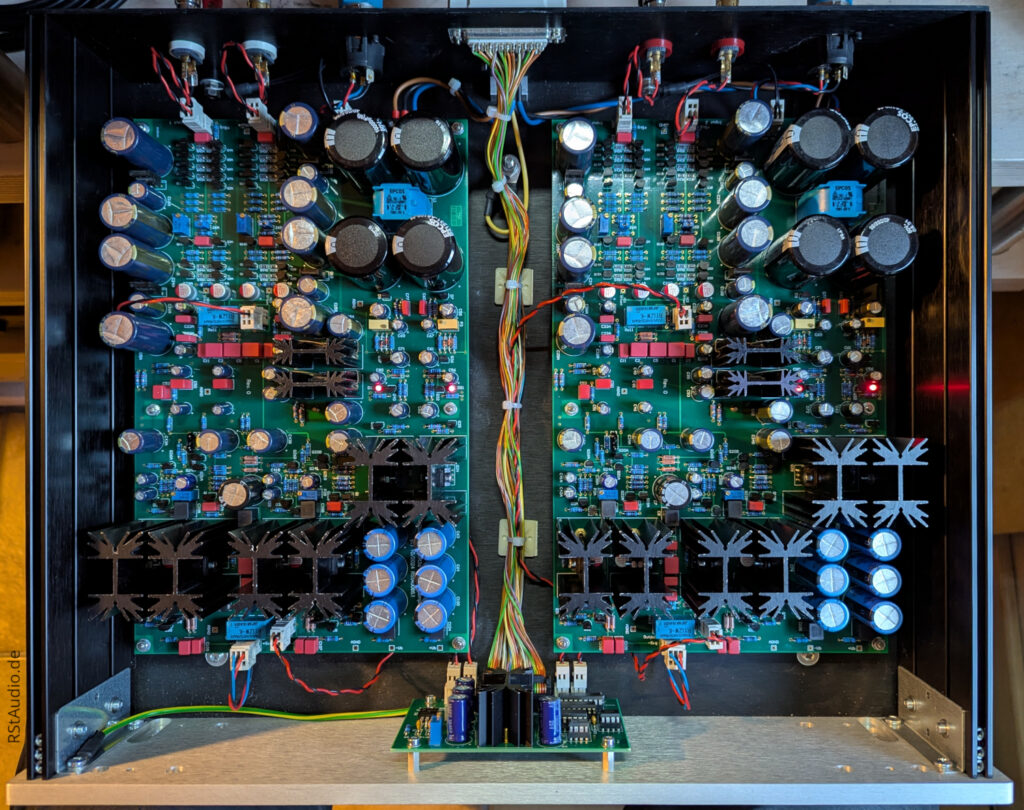
The photo above shows the interior of the VV7/LR from the front. The line preamp circuit board fills almost the entire enclosure. The signal cables running from the backplane to the preamps are individually wired using braided cables. It looks a bit chaotic, but it works perfectly.
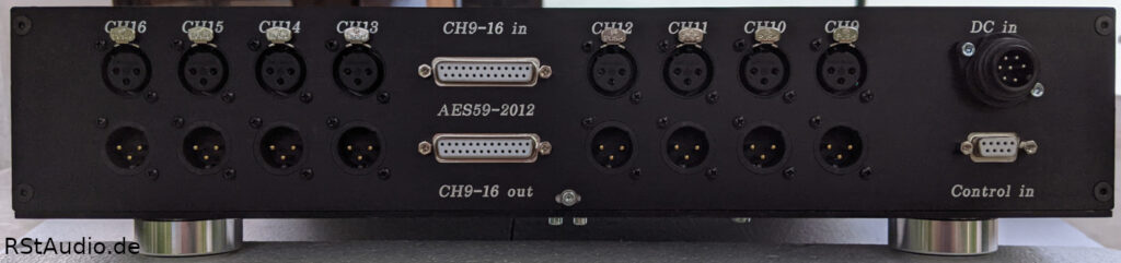
The two Tascam connectors are located slightly off-center on the rear panel. To the left and right of them are the XLR connectors. On the right side are the jack for the DC power supply and the connector for control signals from the VV7/CP.
Controller & DPV1R2 Power Supply (VV7/CP)
January 9, 2022
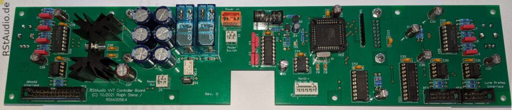
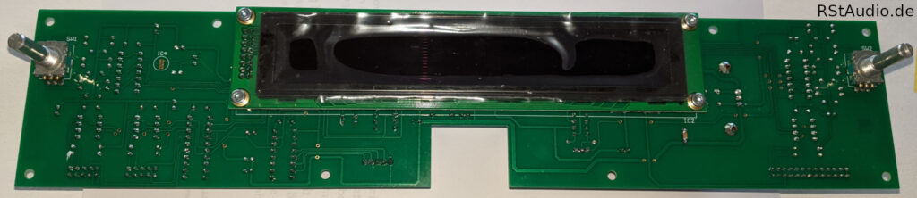
I still prefer to use the AT89C51ED2 as the microcontroller for my audio devices — and that’s the case here as well. With the help of the controller board, the VV7 is operated via two rotary encoders, an IR remote control, and a two-line, 20-column alphanumeric OLED display.
The central button on the front panel turns the preamplifier on and off. However, this only switches the digital components of the VV7; the analog amplifiers are continuously powered. For many years, I’ve found it works best to keep the audio stages of my preamplifier turned on at all times, and this is especially true for the phono preamp. This is particularly important since I listen to music almost every day.
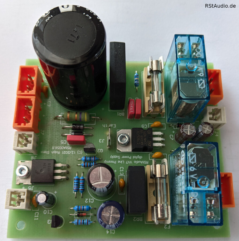
To power the controller board, I use the unregulated power supply from the XOno 2019. I have this circuit board in stock, and as things stand, there is nothing to improve upon.
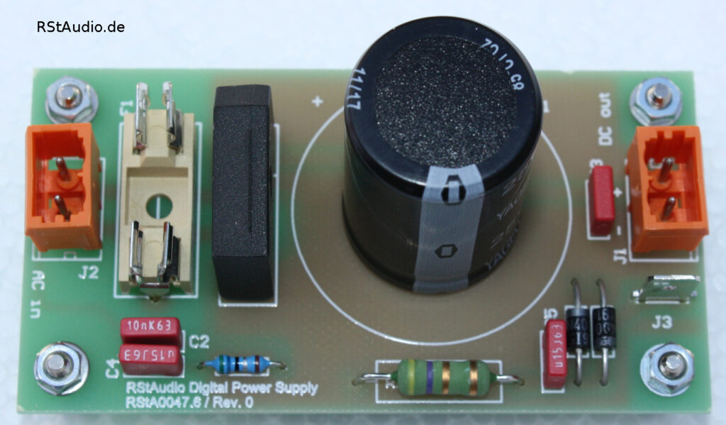
The same applies to the power supply for the two DPV1R2 boards: I also made use of the XOno 2019 project for this. Even today, I still consider the circuitry for the unregulated analog operating voltage to be state-of-the-art. There is absolutely nothing I would change about it.
To power the phono preamps, I use a transformer with separate windings for the left and right channels. Even the best cartridges only offer channel separation of about 35dB — a figure I easily surpass with this design. In this context, channel-separated transformers are unnecessary. As usual, the toroidal transformer used is of excellent quality from Müller Elektrotechnik. Prior to the transformer is a 230V/AC DC filter, also a circuit board from the XOno 2019 project. At the 230V/AC input, I naturally also use an integrated mains filter from Schurter.
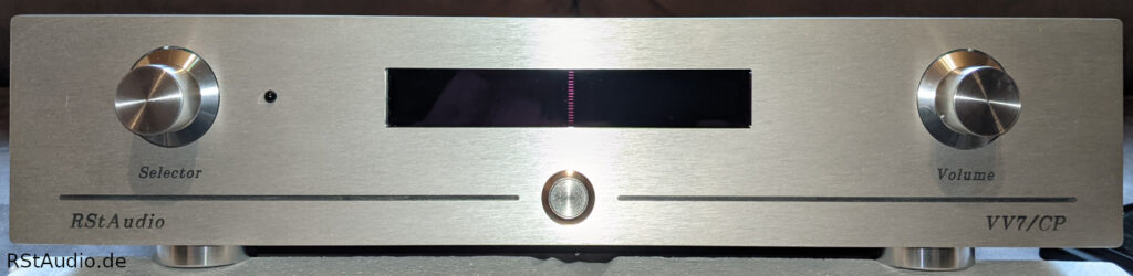
The two rotary encoders are located on the left and right sides of the front panel. The OLED display is positioned in the center, with the button for turning the VV7’s digital electronics on and off located below it. To the right of the left rotary encoder, you can see the IR receiver. By the way, the rotary knobs were provided by my friend Guido.
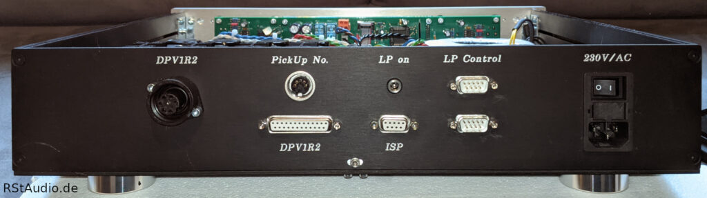
On the left side of the rear panel is the jack for the DC power supply to the DPV1R2 audio electronics. I use industrial connectors from Hirschmann for this purpose. The 25-pin Sub-D jack to the right of it is used to transmit control signals and provide power to the digital control unit, including the relays of the phono preamp.
A number (4-bit binary) is transmitted to the turntable’s motor electronics via the 5-pin DIN jack labeled “PickUp No.” This informs the motor electronics of the selected cartridge. This information is used to determine the run time of the respective cartridge (see #42 Motor Driver).
The DC socket “LP on” carries a control signal used to turn the unregulated power supply for the digital electronics of the line preamplifiers in the VV7/LP on and off. The controller is programmed via the 9-pin Sub-D socket ISP (see Flip). The two 9-pin Sub-D connectors “LP Control” to the right of it carry the control signals for the two line stages (VV7/LL and VV7/LR).
On the far right is the power jack, which houses fuses, a switch, and a power filter from Schurter.
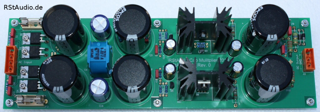
Power Supply for Line Preamplifiers (VV7/LP)
March 11, 2022
This enclosure houses the unregulated operating voltages for the two line preamp boards. Here, too, I made use of the analog voltages from the XOno 2019 project (see above).
Building on the design of the XOno 2019 project, I have expanded the unregulated power supply for the digital circuitry. I’ve added a circuit section that allows me to turn the digital power supply on and off from the controller. I’ve also integrated my Remote Out control. As before, my entire system is to be turned on and off via the preamplifier. Here, too, the analog line stages remain permanently powered.
Unlike the VV7/CP, separate toroidal transformers from Müller Elektrotechnik are used here. There is a 130VA transformer for powering the left and right audio electronics, respectively, and a 23VA transformer for the digital electronics. That’s more than enough power and, as always, oversized — just the way I like it.
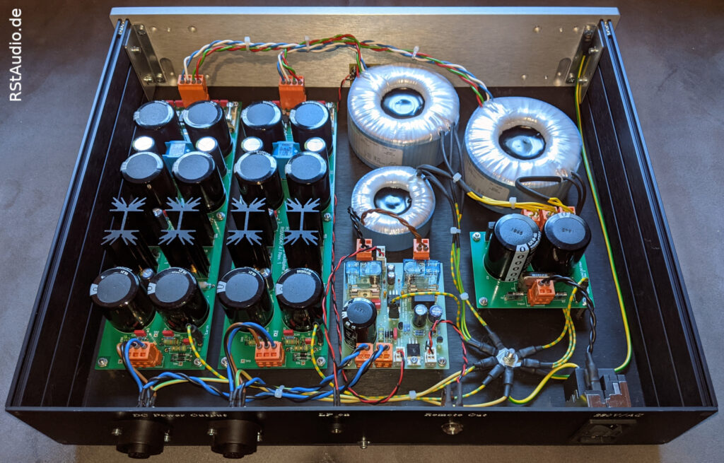
The photo above shows the interior view. On the left are the two boards that power the analog circuitry of the line stages. The unregulated power supplies from the XOno 2019 project, described above, are also used here. The PCB described above, containing the digital power supply, is located in the center at the front. To the right of it is the 230V/AC DC filter. The remaining space is filled by the three toroidal transformers.
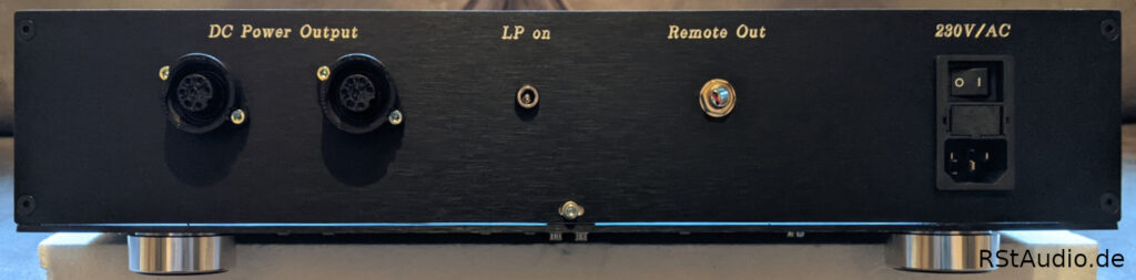
The rear panel of the VV7/LP has a rather simple design. On the left are the two Hirschmann jacks, which carry the analog and digital power supplies for one line stage chassis each (VV7/LL and VV7/LR). The jack labeled “LP on” receives a control voltage from the VV7/CP, which turns the digital circuitry of the line stages on and off. “Remote Out” sends the control voltage for turning the rest of my system on and off. The Schurter power jack is located on the far right.
Audiophile Review
March 24, 2022
DPV1R2
The phono preamp sounded impressively good right from the moment I turned it on. It benefits more than I expected from the Jung regulators. My decision to go through the trouble of upgrading to Rev. 2 was definitely the right one.
May 21, 2022
The VV7 went into operation on my system today. I’m going to listen to it intensively for a while first and then post a review. Since I’m not using any new components, the review will primarily focus on the modified topology.
August 1, 2022
DPV1R2
What I wrote above has been confirmed: The DPV1R2 benefits more than expected from the power supply with the modified Jung regulator. With this power supply, the DPV1R2 ranks at the top of all phono preamps I have heard so far — whether commercial or DIY.
Line Preamplifier
I hadn’t expected any major audiophile improvements compared to the VV5.2. But that’s not the case! I still believe that, when looking at the stages individually, there won’t be any real differences. However, the modified topology has done my system more good than I expected. If you run a system like mine, you have to use a multichannel preamplifier; anything else would only be half the battle.
I am extremely satisfied with the overall result, and as far as preamps go, I’m done with that for now.