… life, the universe and everything …
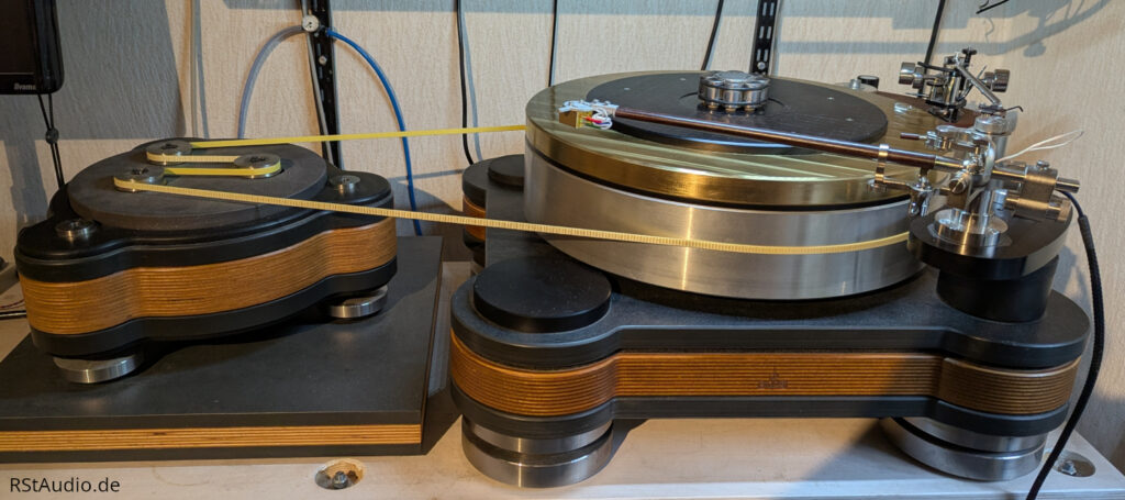
Table of Contents
- Introduction
- Record Player
- The Tonearm Bases
- The Compressed Air System
- The Motor Enclosure
- The Drive Electronics
Introduction
May 30, 2018
When I met Jürgen B. in December 2012, I had already been working on the motor control system for a turntable for some time. At that time, I was using a DIY drive with Scheu components and an ebm-papst motor. I had modified the Scheu platter so that I could measure the rotational speed. Everything was working satisfactorily, and the next logical step — developing my own drive — was supposed to follow. I already had my own approach at that point, but I lacked the necessary professional knowledge to implement the project to my standards. With Jürgen as a partner, however, we then had all the necessary theoretical and practical prerequisites.
We certainly didn’t expect that it would take nearly five years of development and that we’d both have to learn so much about what we thought was a simple topic!
We began developing my drive with the following constraints:
- Mass drive with a platter weight >25kg
- 42 cm platter diameter with maximum inertia
- vertical air bearing
- External motor box with 3 motors
- RPM measurement
- Mounting option for at least two tonearms
- On-the-fly height adjustment of the tonearm bases without a lock
The large platter diameter naturally limits the selection of compatible tonearms, meaning that only 12″ models can be used. While this may be a drawback for many, for me it is simply the logical consequence of my preference for long tonearms.
Anyone wondering why I chose a diameter of 42 cm is either not my age or hasn’t studied electrical engineering, mechanical engineering, or computer science. 42 is the answer to the question of life, the universe, and everything. You can find more information on this here, among other places.
On August 16, 2017, the drive finally replaced my old DIY setup.
Record Player
February 22, 2026
The drive’s construction consists of a range of materials that we selected through testing. These include C45 steel, multiplex wood, slate, aluminum, gray cast iron, and various plastics. The parts are manufactured using various processes such as waterjet cutting, CNC milling, and 3D laser sintering. Above all, however, a great deal of manual work went into the drive, which Jürgen executed perfectly. The surfaces of the materials were not altered — that is, they were neither anodized nor chrome-plated — so as not to affect the specific properties of the materials and thus ensure their proper function. Where surfaces needed protection, a special wax was applied.
The turntable is supported horizontally by a precision bearing with lifetime lubrication provided by solid lubricants and a particularly thick, precision-ground shaft. Vertical support is provided by three air bearings designed to accommodate the turntable’s weight, with a bearing clearance of 5µm. With this bearing arrangement, neither bearing rumbling nor the slip-stick effect occurs.
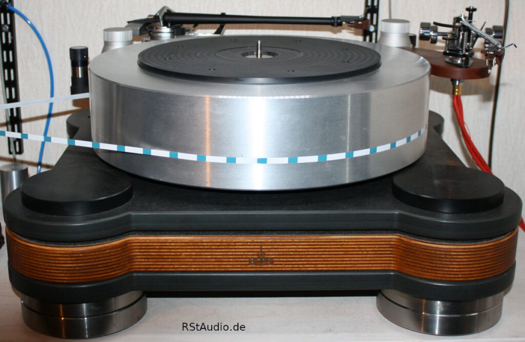
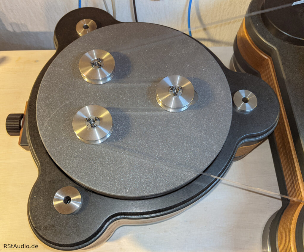
The platter itself weighs approximately 40 kg and is made of aluminum. There are markings on its bottom for measuring the rotational speed. As mentioned above, its diameter is 420 mm. Most of the platter’s mass is concentrated at the outer edge to achieve the highest possible inertia. The record rests on a 10mm-thick, replaceable pad. This allows for experimentation with different materials in this area. For now, I have decided on vinyl (polyvinyl chloride, PVC). The center spindle is placed on the platter without making direct contact with the bearing.
The drive rests on four height-adjustable feet. Each foot consists of two parts connected solely by a ball joint. As a result, the entire drive rests on these ball joints. Damping elements are built into the lower sections of the feet.
Update February 2026
Since it was delivered in 2017, two very unsightly dents have marred the upper edge of the aluminum plate. They were caused by a car accident in which the unsecured, very heavy platter flew through the passenger compartment during an emergency stop. You should be aware of the inertia of such a component and never transport it unsecured!
The idea of milling off the top of the aluminum plate and replacing it with a matching brass part has been on the table for a long time. Unfortunately, this plan has never been carried out over the years. It also always bothered me that the center pin, which is secured to a small round stainless steel disc, simply rested loosely in a corresponding recess in the plate.
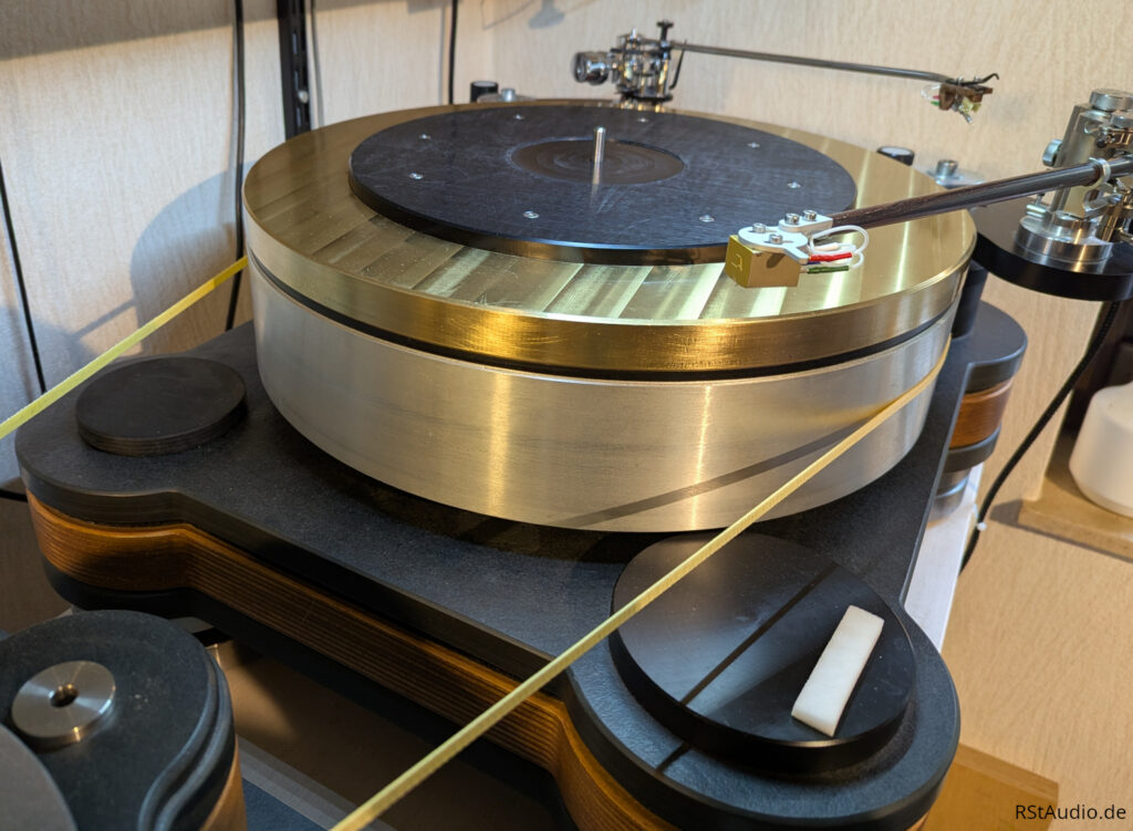
Since mid-2024, my friend Guido has been taking care of all my mechanical needs regarding the turntable. In early September 2025, we sat down together and discussed how we could fix the issues using the plan outlined above. This also involved fixing the center spindle in place. The result was a layered construction of the platter:
- 80mm high aluminum platter
- 5mm thick POM disc
- 24mm high brass platter
- 10 mm thick POM record support
The three platters — made of aluminum, POM, and brass — are aligned with one another by a stainless steel centering piece. The upper end of the centering piece closes with the center mandrel, and its lower end fits into a corresponding recess in the aluminum plate. The record support is screwed onto the brass platter and has a hole in the center with the same diameter as the center mandrel. This additionally clamps the centering piece from above, ensuring that the center mandrel is (finally) firmly secured in its position.
The total mass of the platter has increased significantly due to the use of brass (specific gravity: approx. 8.4g/cm³) and now stands at 56 kg, even though the aluminum platter (specific gravity: approx. 2.7g/cm³) has lost 20mm in height. The three air bearings can easily support the additional weight. To be on the safe side, however, I have increased the air pressure slightly. There is also no need to worry about the horizontal bearing with its thick shaft due to the additional weight. The drive also handles the additional mass effortlessly.
Apart from those two quirks, I’ve always really liked this turntable. But the current platter, with its layered colors, looks absolutely stunning! The turntable has also improved in terms of sound quality, even if it’s just subtle differences.
The Tonearm Bases
March 19, 2022
On my mass drive, the tonearms are mounted on bases that are attached to the sides at the corners of the drive itself. This configuration is also found on many other drives. A fixed mount is attached to a bracket, into which the tonearm is screwed. Ultimately, only this bracket needs to be adjusted to fit the tonearm being used (length, height, and tonearm bore). The correct distance between the tonearm pivot point and the center of the platter is adjusted by rotating the bracket.
My preferred pickup is very sensitive to the VTA setting. This makes the differences in sound between standard records and audiophile-grade records — that is, thicker records — audible.
VTA: Vertical Tracking Angle – more here
So how do you adjust the tonearm correctly? Should you set it for standard records or for audiophile records, to get the best sound from them? Or is a compromise between the two the best solution? After all, you’ve invested a lot of money in a tonearm and a pickup, so naturally you want the optimal setting for every record!
The solution is a finely tuneable height adjustment mechanism for the base, which also needs to work on the fly, so a locking mechanism must be avoided. My drive features exactly this type of height adjustment. The mechanism is designed so that the adjustment works without slop (backlash-free gearing) and the height changes reproducibly with each turn. The base can be adjusted by 8mm in height, which is more than sufficient for any situation.
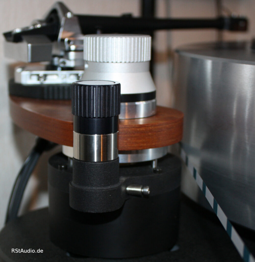
To precisely adjust the height based on the thickness of the record, we still need a suitable measuring device.
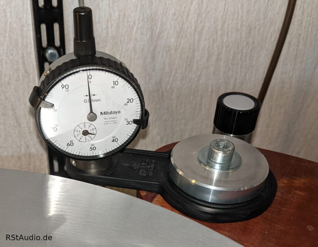
Using a cross-line laser, I align the tonearm so that it is perfectly horizontal. Starting from this basic position, I can then use the dial gauge to reproduce the VTA settings for records of varying thicknesses. In addition, the tonearm needs to be raised slightly at the base to accommodate my cartridge.
The Compressed Air System
September 11, 2017
I measured the residual magnetism on the top surface of a well-known magnetically-bearing drive using a simple compass. The needle showed significant deflections. That was the reason why, years ago, I decided to use an air bearing instead of a magnetic bearing. I definitely didn’t want an additional magnetic field near my sensitive cartridges.
As is well known, compressed air is a very expensive form of energy. If you want to build a system that is as perfect as possible, the cost will be correspondingly high. The system I use consists of a compressor, an air dryer, a 14-liter storage tank with an integrated pressure reducer, and a 0.2-liter surge tank located directly inside the drive. After passing through this vessel, the compressed air is distributed to the three air bearings via a loop line.
I use a very quiet but powerful compressor from the dental industry, which I bought cheaply on eBay. Jürgen came up with a very clever solution for the air dryer. Similar systems were all priced above €1,500. The solution comes from the automotive industry and is normally used in trucks. It even includes an integrated regeneration system for the dryer cartridge — as I said, a very clever solution. However, the whole setup isn’t suitable for a living space and is also too loud to be housed in a listening room. That’s why I keep the entire unit — compressor and air dryer — in the adjacent room.
The Motor Enclosure
December 17, 2020
When I first saw the three-motor design of the Raven Black Night from TW Acustic in Herne, I knew that was exactly what I wanted for my turntable. For me, this three-motor setup is simply the right one.
Although the motor layout is similar to that of the Raven Black Night, the rest of the motor box is more complex in design. The center motor can be adjusted using a knob to optimize the belt tension. This is much more precise than simply moving the heavy motor housing.
In addition, the three feet of the motor box can be adjusted for height. This allows the box to be not only aligned perfectly horizontally, but also adjusted in height to match the center of mass of the platter.
The pulleys are precision-turned and feature a collet in the center that faces the motor shaft. This ensures that the pulleys are perfectly centered and run smoothly. The pulley diameter is selected so that the motors operate in the optimal range at 33.3rpm, meaning they run at the lowest possible speed while delivering maximum torque (which minimizes operating noise).
Before being put into use, the motors were disassembled and their original bearings were replaced with precision bearings. This significantly improved their smoothness of operation. In addition, each motor is individually dampened within its housing. The motor housing itself is lined with damping material all around the inside. Thanks to these measures, the drive system—even with three motors running — is barely audible even from a short distance away.
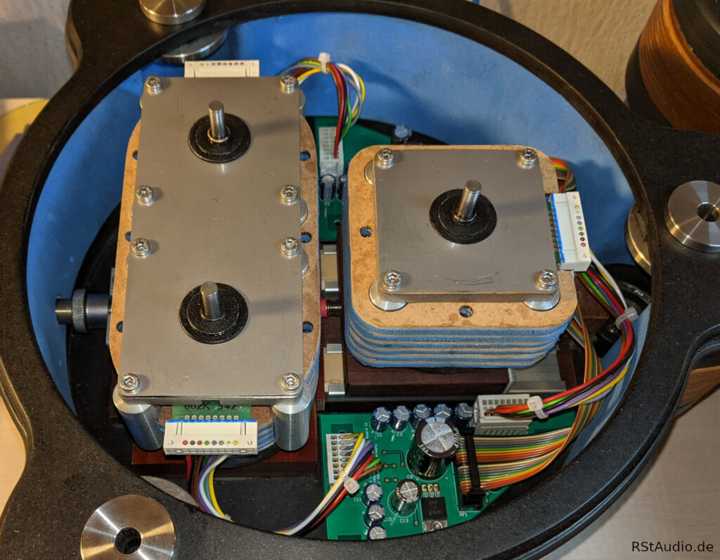
An absolutely brilliant and impressive creation by Jürgen!
The two circuit boards distribute the signals. The numerous capacitors stabilize the operating voltage directly on-site. In addition, driver components for the control signals (SMD devices) are integrated on the bottom side of the circuit boards. The motor box is connected to the motor electronics via a standard 25-pin Sub-D cable. The corresponding connector is located on the underside of the box in a small additional housing that was manufactured using a 3D printer.
The Drive Electronics
November 21, 2022
The drive electronics are based on a C8051F120 x51 microcontroller from Silicon Labs, which I run at the maximum internal clock speed of 98 MHz. It is controlled via a rotary encoder and a two-row, 20-column OLED (Organic Light Emitting Diode) display. The software has grown significantly over the years and has been expanded to include numerous features related to the drive’s operation.
Among other things, I store the operating time of up to five pickups. This figure isn’t 100% accurate, but it’s definitely much more precise than any estimates.
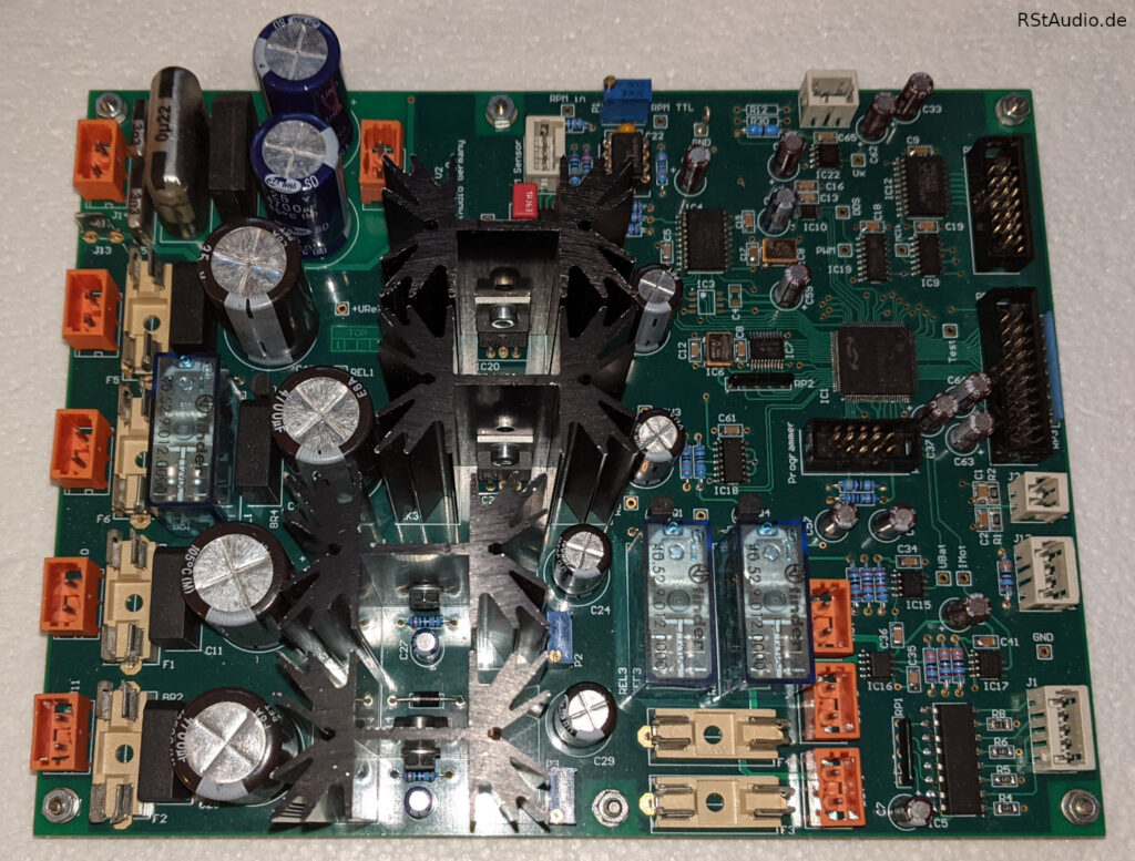
The motors we use feature integrated electronics and require two status signals for control, as well as a square-wave signal whose frequency determines the speed. This frequency is generated using a DDS chip based on a crystal reference. The output frequency for the speed is set in the chip via a 28-bit register, which provides extremely fine frequency resolution.
Optical marks are affixed beneath the platter and scanned using a reflector. Using the resulting measurement signal and a 25MHz reference frequency, the rotational speed is measured with very high resolution in a 32-bit counter register. However, speed control has proven counterproductive for a platter with such high inertia, as the speed is extremely stable even without control. The target speed of the motors is calculated by the software based on the drive’s geometric data and can be slightly adjusted by the user.
During my experiments with the ebm-papst motors, I found that they run much more smoothly when powered by a battery. Since the nominal operating voltage is 24V, I connected two 12V/3.3Ah lead-gel batteries in series. These are gently charged while the drive electronics are turned off. Every time the motors are started, the battery voltage is measured first. If it is below a specified value, the drive cannot be turned on. This prevents the batteries from being deeply discharged. However, this has never happened in all these years, and I am still using the first set of batteries.
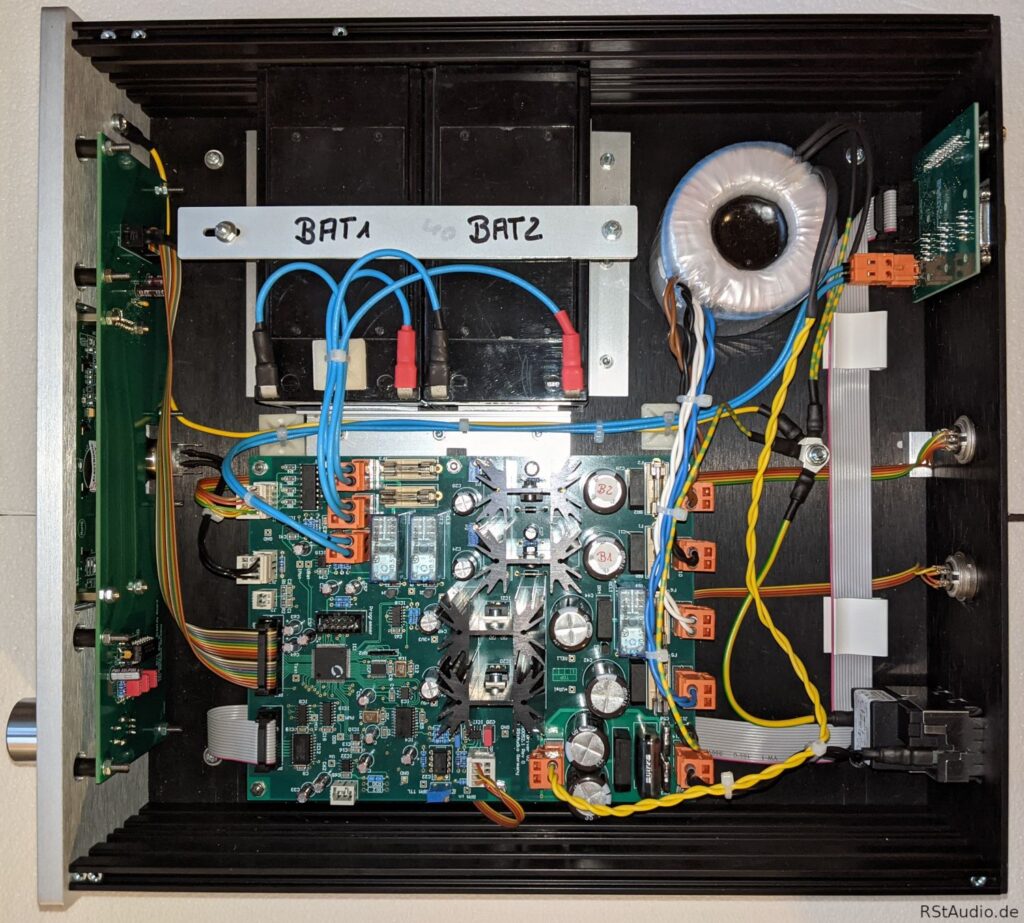
The photo above shows the interior of the motor electronics. In addition to the main electronics board, you can see a circuit board with a display and a rotary encoder, which is screwed directly behind the front panel, as well as a small distribution board for the motor signals, located behind the rear panel. The two batteries are also clearly visible.
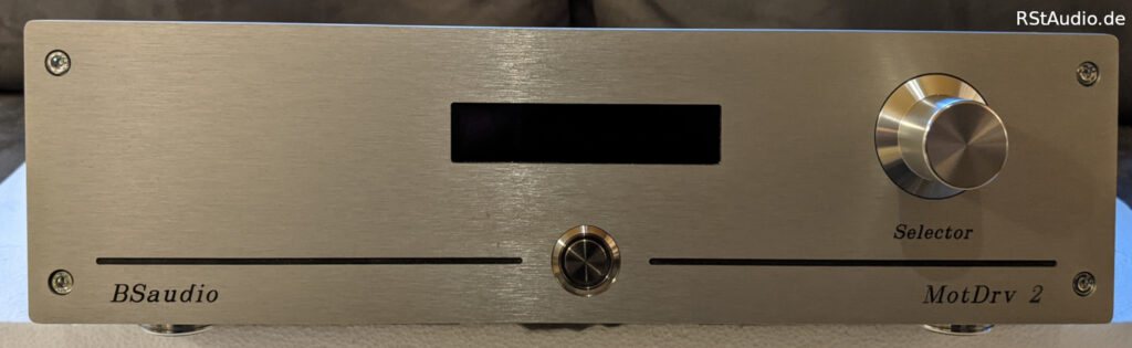
The electronics have very few controls. The pushbutton is used to turn them on and off. The actual operation is handled by the display — which has two rows and 20 columns — and the rotary encoder.
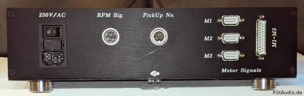
On the back, on the left, is the 230V/AC socket with a filter, fuses, and a switch from Schurter. To the right of it is the input for the speed signal.
The jack to the right of it, labeled “PickUp No.”, is only meaningful in conjunction with my preamps. The preamp uses it to transmit a number for the currently selected pickup. This way, I don’t have to manually tell the motor electronics which pickup’s runtime should be calculated.
The motors are connected to the Sub-D connectors on the far right. You can either connect each motor individually via the corresponding 9-pin Sub-D connector or, as in my case, connect all three motors together via the 25-pin Sub-D connector.