Table of Contents
Project Description
October 8, 2007
Around 1995–96, I came across a description in a newsgroup of a small, very simple amplifier that was used in conjunction with the ’57 Quads. I quickly contacted the author, Sheldon Stokes, via email, and he pointed me to the relevant articles by Nelson Pass. Since the internet hadn’t yet become as widespread back then, it took me two months to obtain copies of the two articles from the American DIY audio magazine The Audio Amateur through my local library. Today, they can easily be downloaded as PDF files from the internet.
- The Pass Zen Amplifier – 10 Watts of Single-Stage Single-Ended Class A
- Return of Zen – Upgrades to the Single-Stage, Single-Ended, Class A Mosfet Amplifier
I could hardly believe that these astonishingly simple amplifiers would work so well with my Quads. However, I was so fascinated by the extremely simple circuit design that I just had to build a pair of these power amplifiers. I’ve been using these small power amplifiers to drive my Stacked Quads for many years (previously, my electrostatic speakers were powered by a modified Quad 405). It wasn’t until 2004 that I had the idea to replace them with a power amplifier offering more power and better adaptation to my specific load—the ’57 Stacked Quads.
The schematic for my Zen power amplifier can be found here.
If I were to build this power amplifier again, I would place greater emphasis on the quality of the coupling capacitors (MKP4, Panasonic FC, Black Gate, etc.). Of course, I would also incorporate the design improvements that have been published in the meantime (Aleph power supply, input buffer, etc.). Nevertheless, this little beast still holds a great fascination for me. For this reason, I have decided to stick with the single-ended Class A concept when building a new power amplifier.
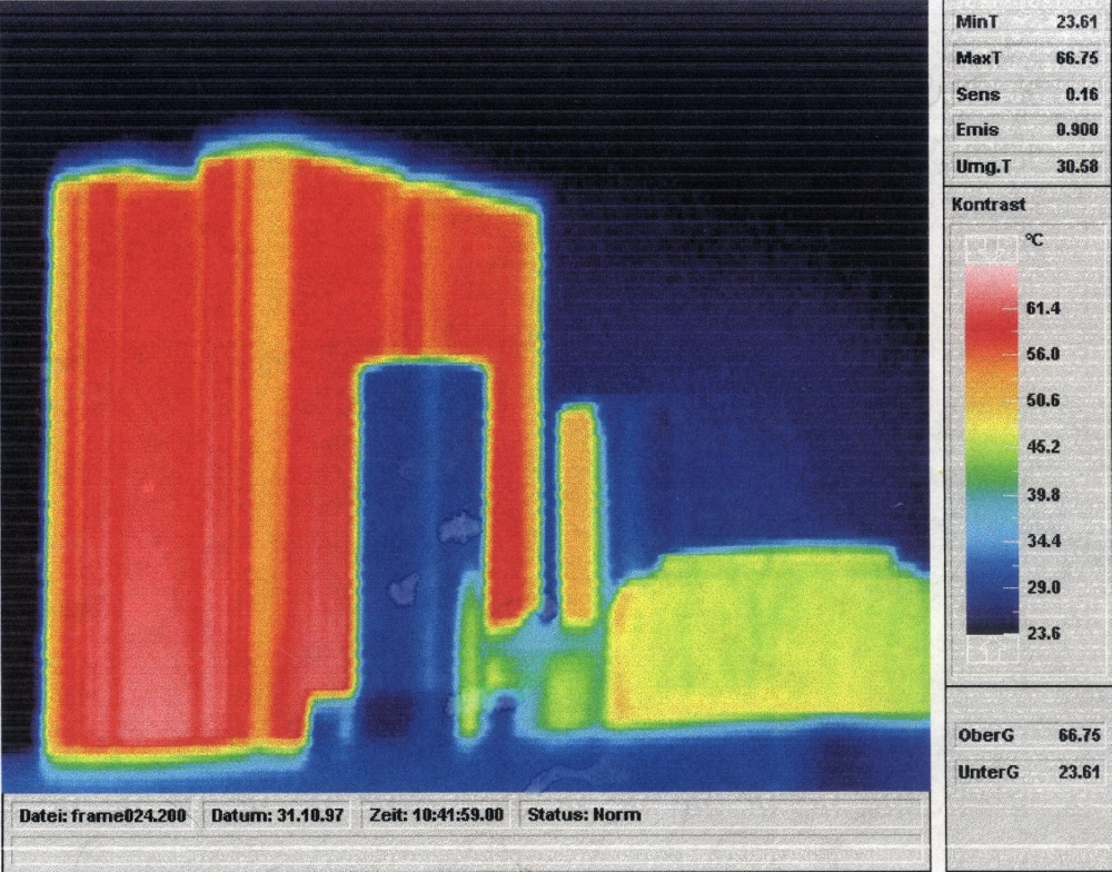
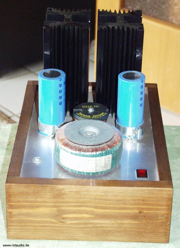
The Zen was my first real experience with a single-ended Class A power amplifier. For this reason, I misjudged the exorbitant power dissipation and used heat sinks that were too small during the initial build (though I was able to quickly remedy this shortcoming). However, the name “Energy Destroyer” stems from this personal realization. In the image above, which was captured with a thermal imaging camera, you can clearly see what I’m talking about.
In building this amplifier, I owe a debt of gratitude to my father, who did a wonderful job crafting the cabinets in the classic design of tube power amplifiers.
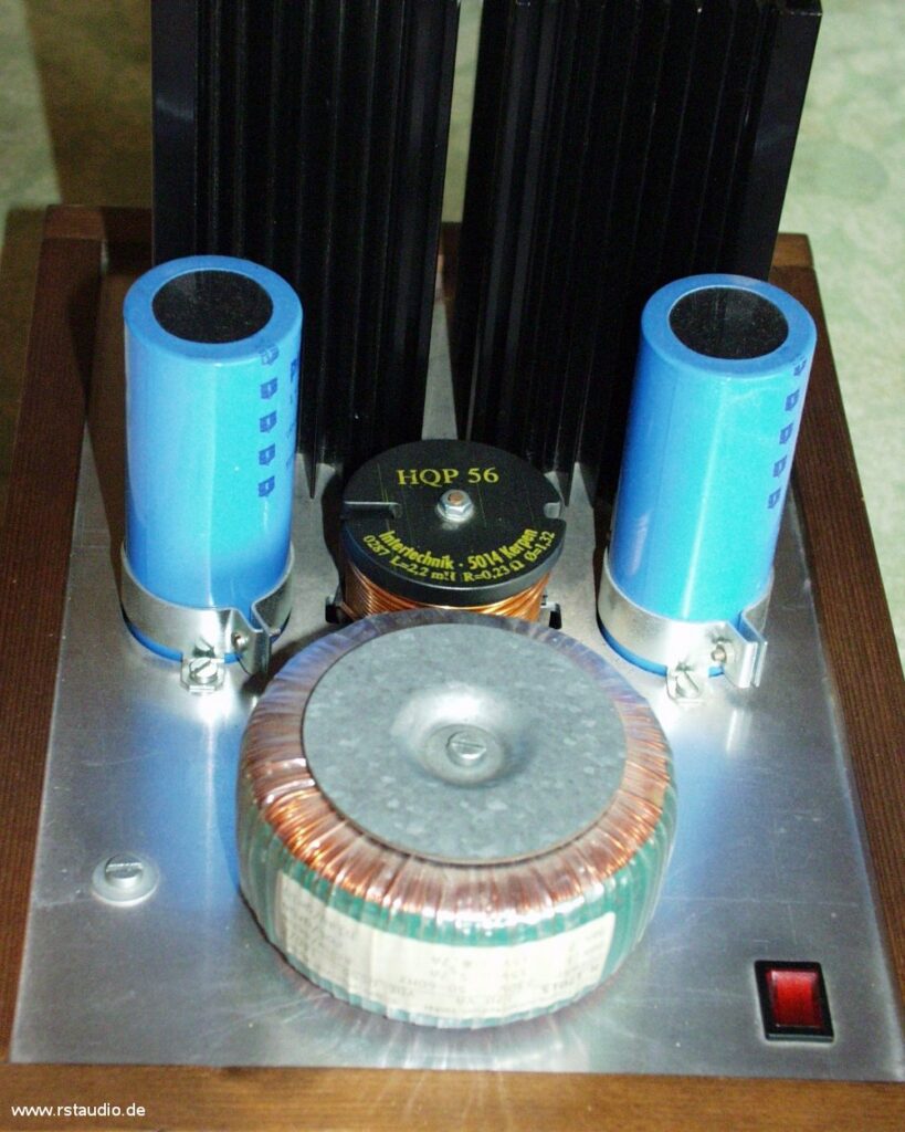
Here you can see the power supply for the power amplifier. It consists of a transformer, a rectifier, and a CLC filter.
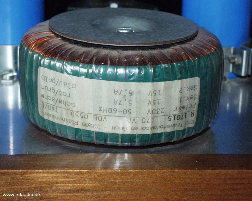
The transformer used is a toroidal transformer rated at 2x 15V/5.7A. The two secondary voltages are connected in series.
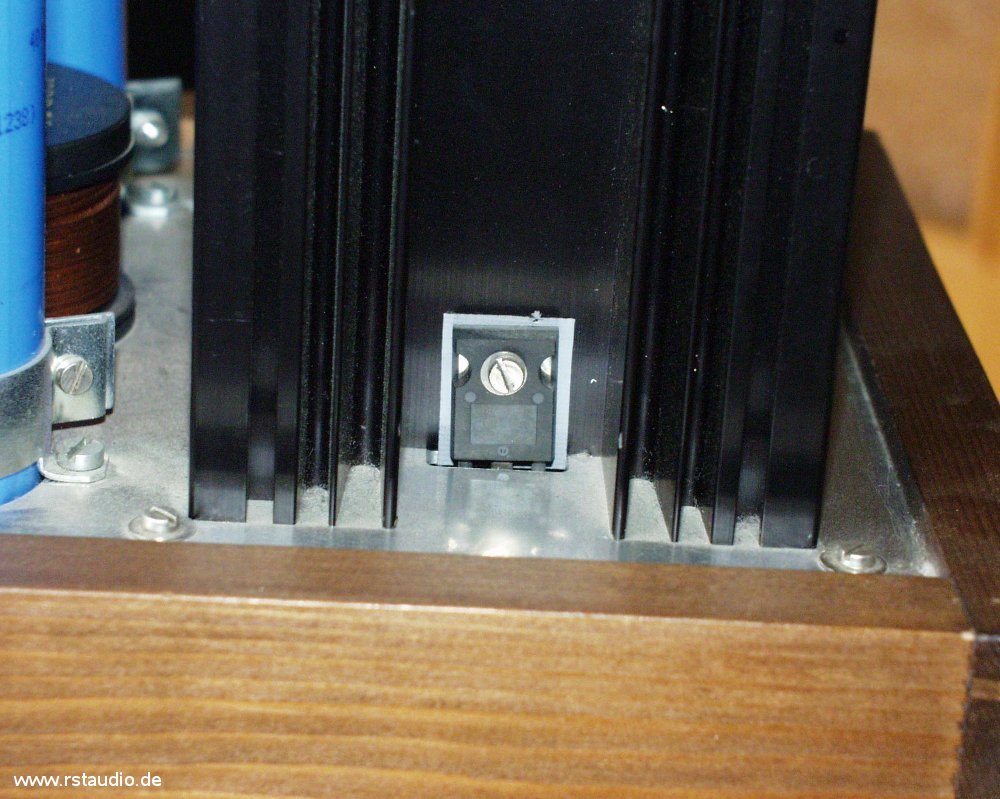
In this photo, you can clearly see how one of the two power MOSFETs is mounted. They are soldered directly onto the circuit board, protrude from the housing through a cutout in the mounting plate, and are screwed onto the heat sink there.
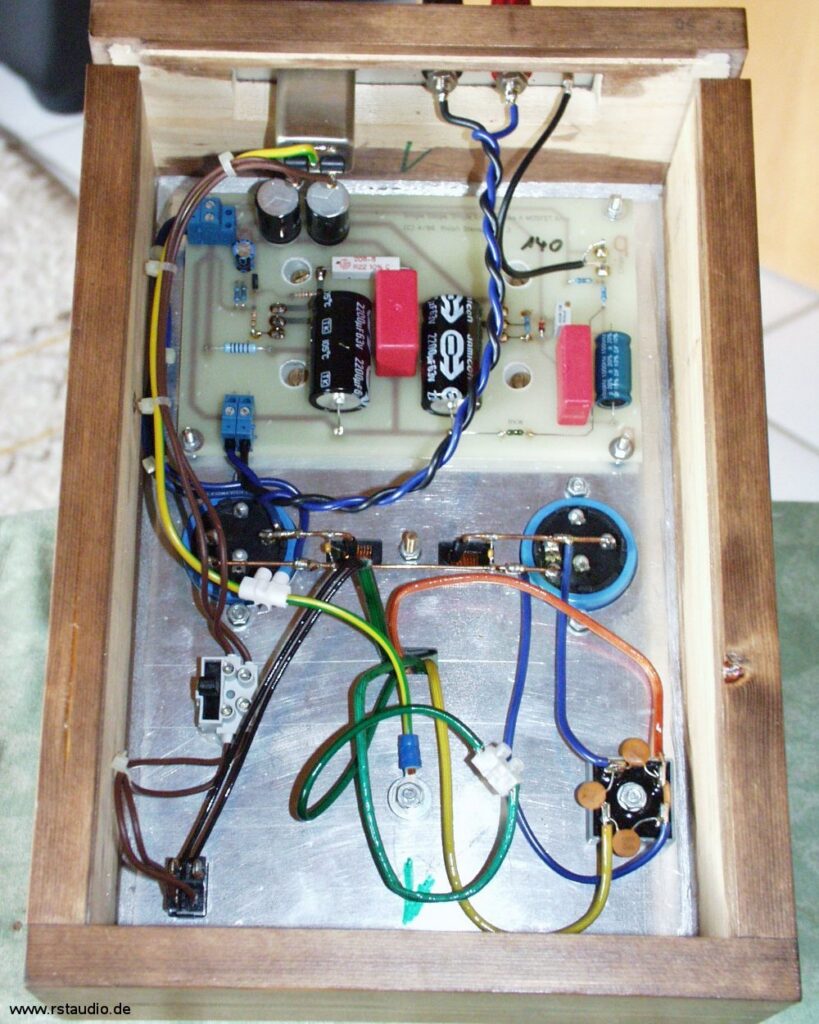
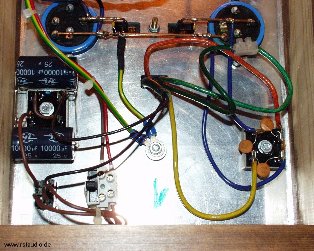
This image shows the entire internal layout. The power switch is located at the bottom left, and the rectifier is at the bottom right. The ground connection is clamped under the transformer’s mounting screw. Above it is the wiring for the CLC filter. On the left side, between the ground connection and the filter, the primary fuse is also visible. In the upper part of the image, the audio board and the components on the rear panel are visible.
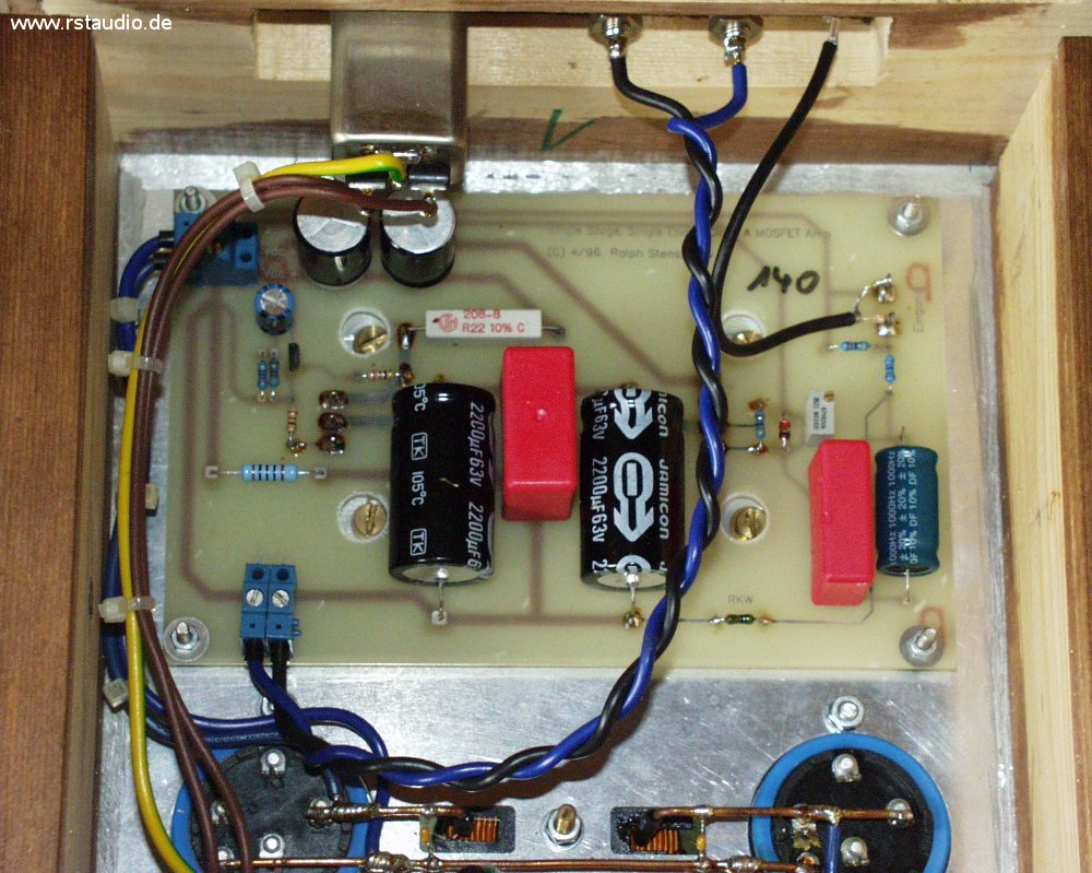
This is an enlarged view of the audio circuit board. The DC power input is located at the top left, and the speaker output is at the bottom left. The signal input is on the right side.
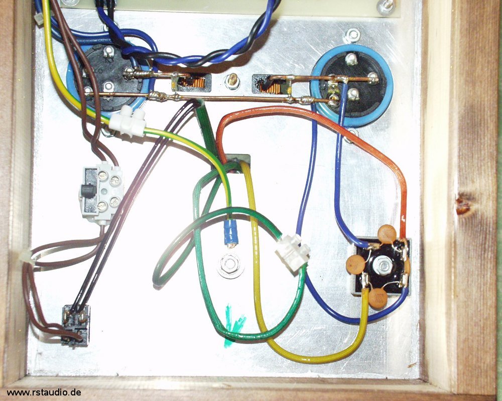
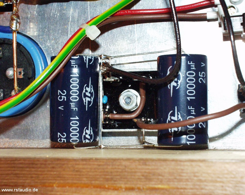
Here is a close-up of the power supply. The ground wire consists of a solid, bare copper wire around which the ends of the connected wiring were wrapped and then soldered. On the right is the capacitor behind the rectifier, while the left capacitor is located at the output of the power supply. The single-pole, floating terminal block to the right of the ground terminal connects the two secondary voltages in series.
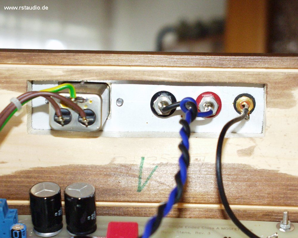
Last but not least, the components on the back of the enclosure are visible. On the left, you can see the power input with a filter. In the center are the two speaker terminals. Finally, on the right side, you can see the RCA jack for the input signal.
DC Filter Expansion
October 8, 2007
In my Aleph P, I had installed a DC filter before the power supply’s transformer and was very impressed by the improvement in sound quality that occurred, contrary to my expectations. So it made sense to equip the Zen power amplifier with a similar filter as well. Here, too, I used a bridge rectifier, though the electrolytic capacitors used have a higher rating (2× 10mF/25V). The result is astonishing. The improvement is significantly greater than with the preamplifier and is particularly noticeable in the bass range.
The DC filter can be seen in the center of the left side of the image. The electrolytic capacitors are soldered directly to the bridge rectifier.
Here is a close-up of the DC filter. The small light-blue capacitor is a 100 nF type.
Muting Circuit
October 8, 2007
The Zen power amplifiers had the unpleasant tendency to send a distinct and relatively loud pulse to the speakers when turned on. To prevent this, I installed a relay that short-circuits the speaker output when the amplifier is idle.
The relay is driven by an IRF610, whose gate is connected to the supply voltage via an RC circuit. This circuit also determines the time constant for the turn-on delay. However, to prevent the full 40V of the supply voltage from reaching the gate — which would certainly destroy the MOSFET — the gate voltage is limited to 11V by a Zener diode. The 2W resistor still visible on the circuit is connected in series with the relay coil and, with its voltage drop, ensures the correct coil voltage. All in all, it is a fairly simple but effective circuit that ensures my power amplifiers now behave very well when switched on.
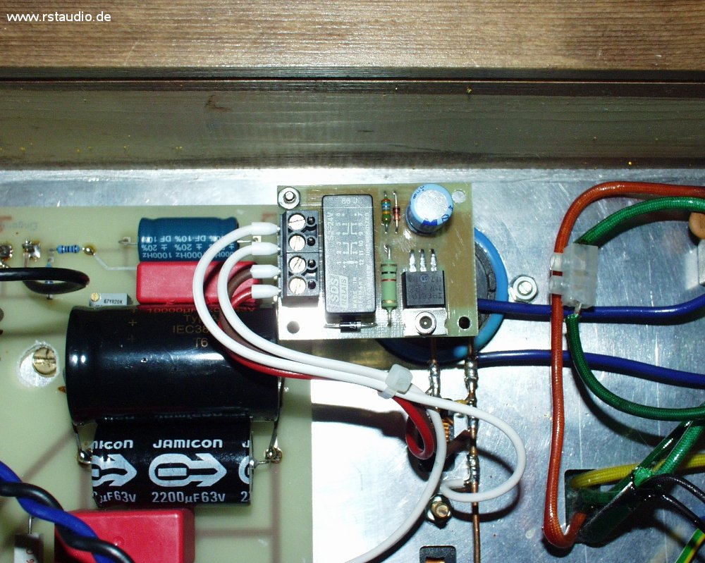
The photo also clearly shows that I have supplemented the original 2,200 µF capacitors (two of them) with a 10,000 µF electrolytic capacitor.