Table of Contents
- Introduction
- Input Board with UGS5 Module
- Output Board of the Bridge Output Stage
- Power Supply
- Inrush Current Limitation and Remote On/Off
- Initial Commissioning
- Changes to the Design
- Converting to a XA30.8
Introduction
May 26, 2013
I’ve had the schematics for Pass Labs’ X.5 and XA.5 power amplifier series for quite some time now. Since I still needed power amplifiers to complete my speaker system, it made sense to choose one from this series. Naturally, it had to be capable of driving my Quad ESLs, and its performance specifications should therefore be tailored to these speakers. I chose the XA30.5, especially since it is a stereo power amplifier and I have had very good experiences with individual speaker control in the Stacked Quads.
The XA30.5 is a stereo power amplifier operating in push-pull AB mode with a maximum output power of approximately 100W/8Ω per channel. However, the published specifications mention an output power of 30W/8Ω. This refers to the output power in push-pull Class A operation. It is therefore a power amplifier with a very high quiescent current. Additionally, there is a circuit section that ensures the power amplifier operates in single-ended Class A mode at low output power levels.
At the input of the power amplifier is a UGS module featuring the well-known SUSY (Super Symmetric) circuit. This circuit topology is only effective when balanced signals are used. Consequently, this amplifier is a bridge-connected power amplifier in which the loudspeaker is placed between the outputs of two power amplifier modules driven in opposite phases. Only in this way can the special feedback technique of the SUSY circuit be optimally utilized all the way to the loudspeaker.
This supersymmetric circuit topology is described in the following patent.
- Amplifier With Gain Stages Coupled for Differential Error Correction
Nelson S. Pass
US 5376899, Feb. 4, 1994
Input Board with UGS5 Module
July 21, 2013
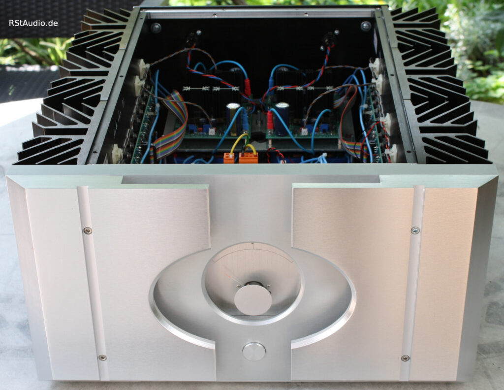
This board houses the input circuitry with selectable voltage gain (24dB or 30dB), the bypassable AC coupling, the UGS5 module, and the two bias circuits for the bridge output stage.
You can clearly see the four trimmers used to adjust the power amplifier. The two trimmers in the middle control the absolute offset of the two outputs relative to ground, as well as the differential offset between the two outputs. The two outer trimmers are used to set the quiescent current of the two sections of the bridge power amplifier.
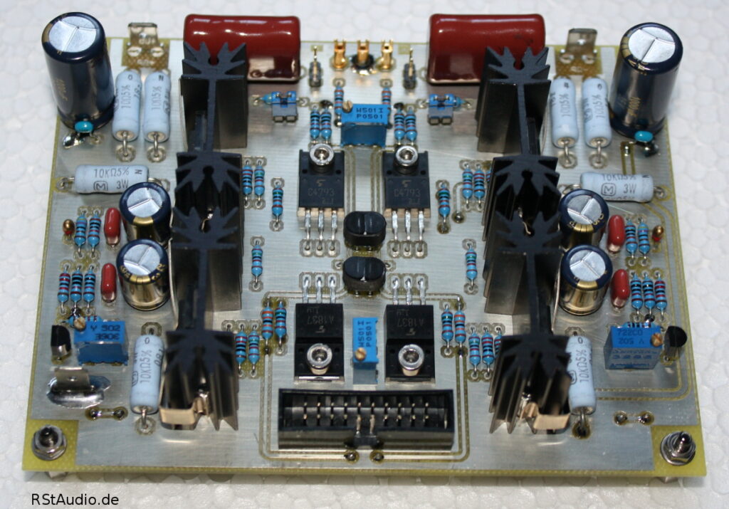
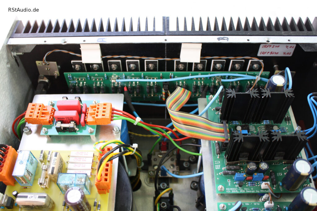
Output Board of the Bridge Output Stage
September 28, 2013
The output board, with its 20 power MOSFETs, is mounted directly on the heat sink. The layout of the circuit board shows the two sections of the bridge output stage, each containing 10 MOSFETs. The power resistors to the left and right of the board are part of the circuitry for single-ended Class-A operation of the output stage. A thermal switch is also mounted on the left side of the heat sink, which shuts down the output stage as soon as the heat sink exceeds a temperature of 75°C.
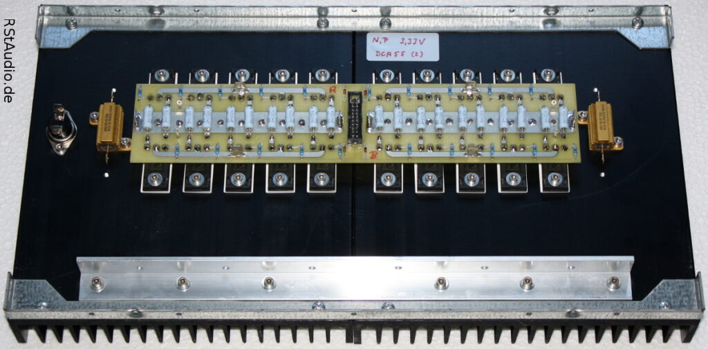
In the final design, I did not use the simple circuit with the resistors. Instead, I used a slightly more complex circuit, similar to the one found in the newer power amplifiers from Pass Labs.
This technique can be applied to all push-pull power amplifiers. A very good introduction to this topic can be found in the book
Audio Power Amplifier Design Handbook – 5th ed.
Douglas Self
Focal Press
ISBN: 978-0-240-52162-6
in the chapter 11 Class-XDTM: Crossover Displacement Technology.
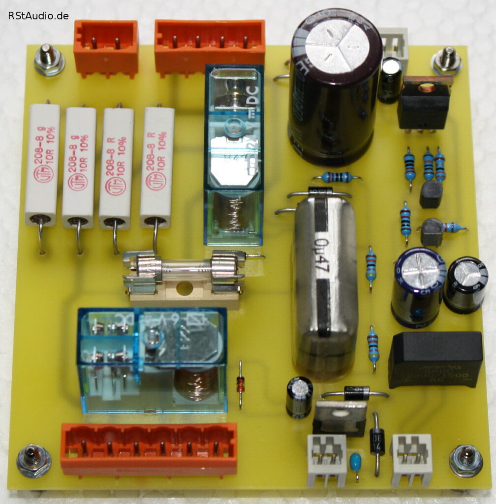
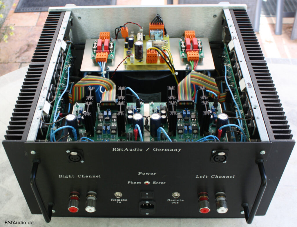
Power Supply
September 28, 2013
In power amplifiers in particular, the power supply determines the audiophile quality of the device. For this power amplifier, I also chose a dual-mono design — with the exception of the transformer. This means that each channel has its own power supply. Although there is only one transformer, it has separate windings for each channel.
As is standard practice with all my devices, I’ve installed a DC filter in the transformer’s primary input line. I describe in detail how to design such a filter in the “Tips & Tricks” section. Here, I’m using four 22,000µF/25 V electrolytic capacitors, since I have them available in large quantities.
The power supply design for each channel is conventional. A snubber network is installed behind the fused secondary windings of the transformer, which strongly dampens the resonant circuit — consisting of the transformer’s secondary coil and the reverse-bias capacitance of the diodes in the bridge rectifier. This is followed by a discrete bridge rectifier with ultrafast soft-recovery diodes from International Rectifier (HFA25PB60). This is connected to an electrolytic capacitor bank with a capacity of 4x 47,000µF and 2x 0.22Ω/25W for CRC filtering. I can only use the CRC topology here because I am certain that my speakers will not cause the power amplifier to leave the Class-A range — in Class-B operation, modulation of the music signal would occur across the resistors.
Inrush Current Limitation and Remote On/Off
September 22, 2013
Starting at around 400VA, toroidal transformers have such high inrush currents that they typically trip a standard household circuit breaker. For this reason, these so-called inrush currents must be limited. The board shown here is also used in the Aleph J and in the Hypex power amplifier. The circuit has proven itself over the years.
In addition to the current limiter, the board also features two circuit sections that allow the power amplifier to be turned on and off using a remote DC voltage, as well as enabling the delayed switching of another device.
The schematics for this board can be found in the description of the Hypex Class-D power amplifier.
Initial Commissioning
August 21, 2019
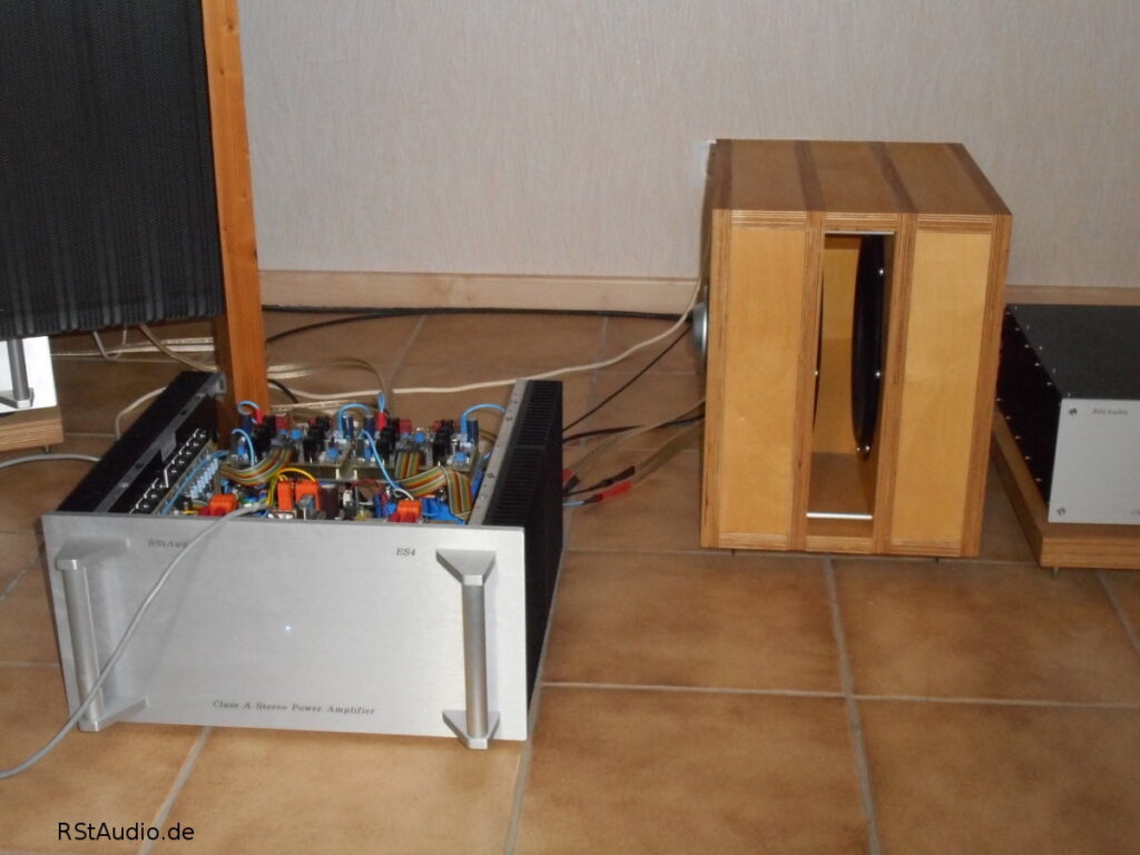
The initial setup — still without the rear panel — took place on March 23, 2014. The first impressions were rather sobering: Compared to the Aleph J, the XA30.5 performed less well. Four days later, however, the first “aha” moments began to emerge, and two days after that, it was clear where things were headed. The XA30.5 requires some break-in time.
By now, I would rate the comparison with the Aleph J similarly to the comparison between the X0.2 and XP-30 preamps. I’ve enjoyed listening to music with the Aleph J for several years and have been very satisfied with it; it is without a doubt an outstanding power amplifier. However, when comparing it directly to the XA30.5 — currently I only have a stereo power amplifier in the system, meaning the two Quads per channel are running in parallel on a single channel of the XA30.5 — it becomes abundantly clear which power amplifier takes precedence. As with the preamps, the XA30.5 stands out for its resolution and richness of detail — it’s simply indescribable and, for me, impossible to put into words.
I am constantly amazed at the progress that is still possible.
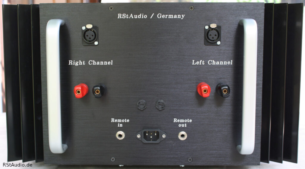
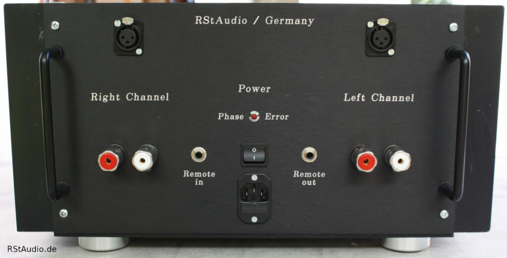
The following image shows the rear panel of the ES4 with its inputs and outputs.
Changes to the Design
July 24, 2018
Of course, as is usual with my replicas, I have made a few changes to the original XA30.5 schematics. I have schematics from 2007, so I am referring here to the design of the XA.5 series at that time.
I made the biggest changes to the power supply. I designed it entirely on my own and only referred to the XA.5 series schematics for the most important specifications: the output voltage and current.
- Originally, there is only one power supply for both channels. In my setup, it’s a dual-mono configuration starting from the secondary side of the transformer.
- The total capacitance of the original power supply is 180,000µF; mine is 376,000µF.
- The passive power supplies are equipped with CRC filter stages; in the original design, they consist only of capacitors — see above for the reasons.
- On the primary side, I used a 230V/AC DC filter.
- Instead of a simple NTC solution, I use a small sequence controller as the inrush current limiter for the transformer. This completely shuts off the current-limiting element, preventing any unnecessary heat generation.
- I have installed a snubber network on all secondary-side voltages. This prevents a high-frequency resonance frequency from developing on the DC voltages.
- There is a circuit component that remotely turns the power amplifier on and off.
I’ve also made some changes to the audio circuitry.
- The AC input coupling can be bypassed on my unit.
- The operating point of the two JFET differential amplifiers in the UGS5 module has been optimized.
- In the UGS5, I use a Hawksford Kaskode. This further reduces distortion.
- At the output of the UGS5, I use Toshiba MOSFETs, as in the newer designs from Pass Labs.
- For the single-ended Class A output stage, I don’t use the simple resistor network.
- I have increased the single-ended Class A output power many times over compared to the original.
Converting to a XA30.8
August 21, 2019
In mid-2016, I converted both power amplifiers to the XA30.8. To do this, I had to redesign both audio circuit boards, with the most significant changes made to the front end.
Surprisingly, the audiophile performance has improved yet again. While the difference between the XA30.5 and the XA30.8 isn’t as significant as the one between the XA30.5 and the Aleph J, I’m always amazed at how even small design changes can further enhance a device’s performance.
For my friend Guido, I built a power amplifier in a chassis modeled after the X.5 series and manufactured in China. The chassis itself weighs about 20 kg, so this power amplifier is quite unwieldy due to its size and weight. However, it’s a real treat for the eyes, and I never tire of admiring its design — as long as I don’t have to move it.