Table of Contents
Introduction
November 10, 2019
My active crossover contains circuitry that allows for frequency-dependent signal modulation in the subwoofer channel. However, analog circuitry offers only limited possibilities for this compared to the digital signal processing of a DSP (Digital Signal Processor). Since I had a miniDSP 2×4 board left over from another ongoing project — an active absorber — I decided to use it for a subwoofer equalizer.
When used as an equalizer in the mono subwoofer channel, only one input and one output of the DSP board are required. The second input and the three additional outputs of the miniDSP therefore remain unconnected and are disabled in the accompanying software.
The entire assembly consists of the following components:
- miniDSP 2×4 Kit with Advanced Plug-In
- 1 balanced input
- 1 balanced output with amplification
- 1 Power Supply for Analog Circuitry
- 1 Power Supply for the miniDSP and the Remote Power Supply
- Remote On/Off
Hardware Description
March 25, 2018
Information about the DSP board can be found here. You can learn more about the software plug-in here.
The entire audio circuit can be bypassed using a relay. In this case, the input is connected directly to the output to route the signal passively through the SubDSP. The relay is activated via a switch on the front panel of the enclosure.
The balanced input signal is converted to the unbalanced input of the miniDSP board using an INA134 (audio differential line receiver). At the input of the line receiver, there is a voltage divider that serves as an input resistor and is used for level matching to the DSP board. The jumpers on the miniDSP board for input sensitivity must be set to 2VRMS.
The output signal from the miniDSP is routed via an AC coupling (C14) to a 4th- or 8th-order Butterworth low-pass filter (jumper J4) with a cutoff frequency of 250 Hz and a gain of VU=2. AC coupling is necessary because the output signal from the miniDSP — at least on my board — is not free of DC voltage. The low-pass filter reliably suppresses the RiPol’s resonance frequency, which is around 300Hz. The levels at the DSP board’s outputs are not particularly high — max. 0.9VRMS — which is why the filter has a gain greater than 1.
The analog power supply consists of a 10VA toroidal transformer, followed by a snubber network and a discrete bridge rectifier. This is followed by a classic voltage regulator circuit using 7815 and 7915 regulators. As a special feature, I use NJM voltage regulators here.
To integrate the SubDSP into my system, I also needed a way to remotely power the device on and off using a DC voltage. In addition, a DC voltage is required to power the miniDSP board. These voltages are supplied by the second power supply on the circuit board.
The power supply for the DSP board is simpler than the analog power supply; it has no snubber network and no discrete bridge rectifier. The ground of the DSP power supply is connected to the ground of the analog power supply.
The remote control circuit is now included in all of my devices and allows me to turn the entire system on and off using the preamplifier. All connected devices are daisy-chained, and each device triggers a time-delayed power-up of the next one in the chain. This ensures that, for example, two power amplifiers do not simultaneously overload the household electrical circuit with their high inrush currents.
The circuit around IC7 is the input, i.e., Remote In. The DC input voltage from the preceding device is regulated to 6V by the voltage regulator, which then activates relay REL1. This relay switches on the 230V/AC power supply to the SubDSP. The relay is bypassed by a power switch, so the device can also be turned on and off in the traditional way using the power switch.
The second part of the circuit generates the time-delayed DC voltage for the downstream device — Remote Out. The unregulated DC voltage is switched to the output via Q1. Q1 is turned on with a time delay by Q3. The time constant is defined by R15 and C42. Q2 serves as a current limiter to prevent Q1 from being damaged in the event of an operating error.
- Circuit Diagram of the symmetrical In- and Output
- Circuit Diagram of the Low Pass Filter
- Circuit Diagram of the Power Supply
- Circuit Diagram of the Analog Power Supply
- Circuit Diagram of the Remote on/off
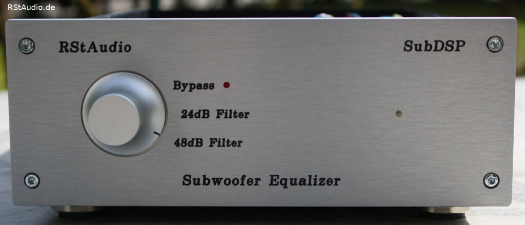
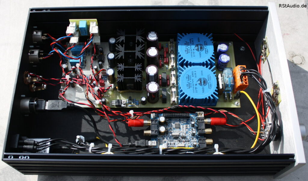
The following picture shows all the electronics installed in the enclosure. As is usually the case, I’m using an enclosure from HiFi-2000. At the top of the image you can see my electronics; at the bottom is the miniDSP board. On the front panel there is a rotary knob that allows you to select between bypass, 24dB filter, and 48dB filter. The bypass setting is additionally indicated by a red LED.
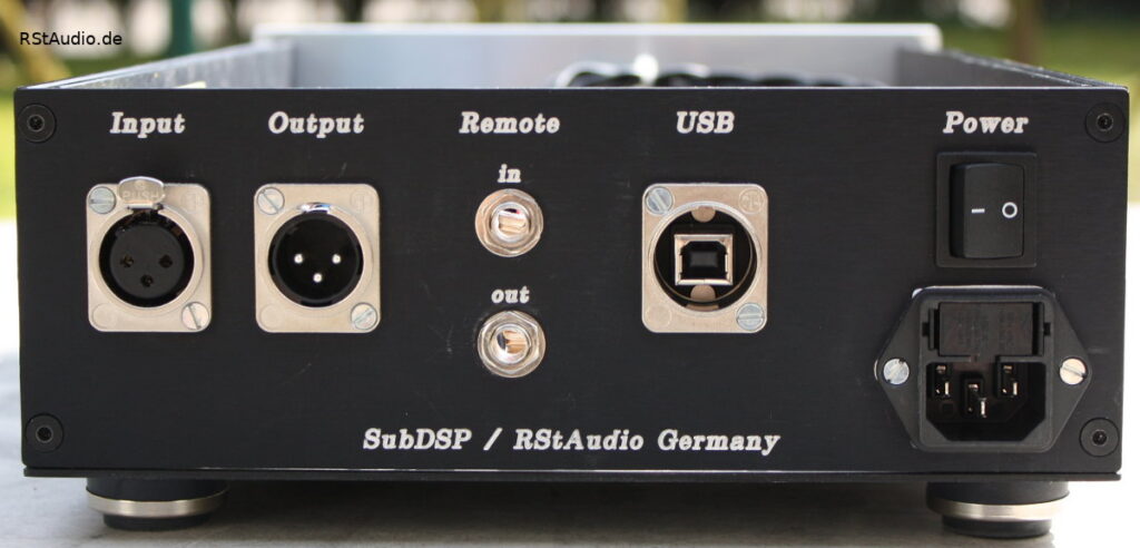
The next image shows the rear panel of the SubDSP. On the left are the two XLR jacks for the audio input and output, followed by the two 6.3mm mono jack sockets for remote control. Next to these is a USB port, which is used to program the miniDSP. On the right is the 230V/AC power supply. I don’t usually use the power switch; the unit is typically turned on and off via the remote DC voltage.
Calibrating the miniDSP
January 17, 2018
A project like this only makes sense if you are able to take measurements of the listening room. To do this, you need
- a PC
- a high-quality sound card
- a microphone preamp
- a measurement microphone — preferably with calibration data
- a microphone stand
- software for measuring room acoustics
Setting up a system like this requires some experience — which, unfortunately, I’m only gaining very slowly. You have to be able to interpret the measured curves correctly in order to determine the appropriate settings for the DSP. Fortunately, my friend Heiner is an expert who can help me configure the system properly.
I use the SubDSP to correct my room modes by attenuating the level in those frequency ranges. However, such a system alone is not capable of making accurate corrections; after all, the bass energy generated by the modes is still present in the room, even if it is attenuated by the SubDSP settings. Only in combination with the Active Absorber are the room modes effectively dampened.
The overall result achieved with SubDSP and the active absorber is very impressive, and I’m able to achieve reverberation times that are nearly optimal for the listening room. There’s no more rumbling in the bass reproduction, and all instruments can be clearly distinguished from one another. Once you’ve gotten used to a system like this, room resonances during playback — for example, at trade shows — immediately stand out and become unbearable. I’m actually no longer able to listen to a system comfortably if no measures have been taken to correct the reverberation.