Table of Contents
Introduction
July 17, 2007
In 2006, I happened to meet another very dedicated DIY enthusiast via email. After an intensive exchange of information, he provided me with the service manuals for the Pass Labs X0 preamplifier. At first, I was simply curious about how the volume control using bipolar transistors worked in this series of Pass Labs preamplifiers. After studying the schematics, I was, of course, unstoppable and began developing the concept for my next preamplifier (VV4) based on a replica of the X0. In doing so, I wanted to incorporate some elements from my Aleph P preamplifier as well as the Pass Labs XOno replica. The result is a concept that spans four enclosures.
- Audio Unit
- Pass Labs X0 Preamplifier with electronic volume control
- 5 inputs and a tape loop controlled by relays
- Muting relay at the output
- Regulation of operating voltages
- Standby mode
- plug-in digital control board
- Digital connection of the control module via the I²C bus
- Unregulated DC power supply from the control unit
- Phono Unit
- Pass XOno Phono MC/MM Preamplifier (Replica)
- Unregulated DC power supply from the control unit
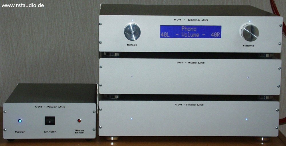
- Control Unit
- Controlling the Preamplifier via Microcontroller / Design of the VV3
- Digital connection of the audio module via the I²C bus
- Unregulated DC power supply for the audio and phono unit
- Power Unit
- Transformers for supplying operating voltage to the VV4
- DC filter for the 230V/AC power supply
- Power filter for suppressing high-frequency interference
- Detection of the correct power phase via LED
On April 19, 2008, the VV4 replaced the VV3/Aleph P replica.
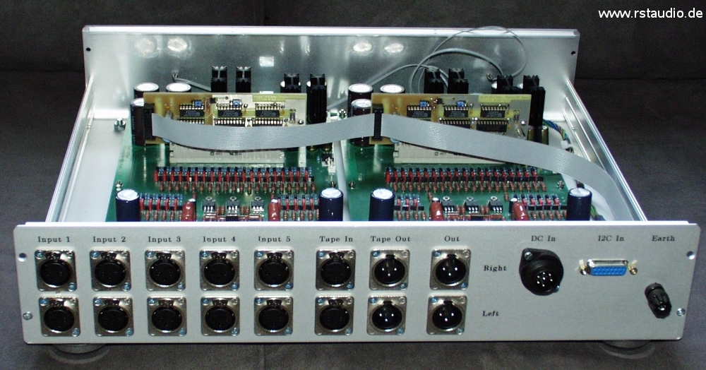
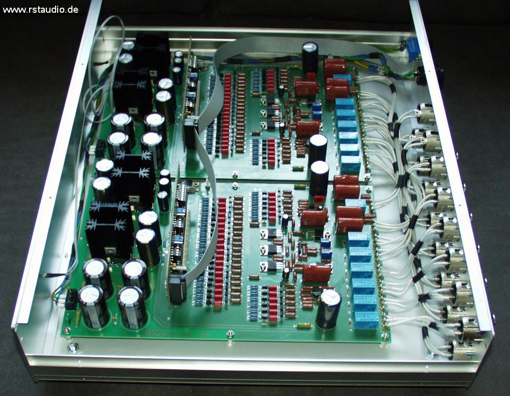
Audio Unit
April 10, 2008
At this point, I would like to extend my special thanks to Mr. S. from H+S Leiterplatten Service.
Without him, I wouldn’t have known at the time how to have such a large circuit board manufactured.
At the heart of this Audio Unit is a replica of the Pass Labs X0 preamplifier.
All FETs and MOSFETs are matched. I borrowed the input selection circuit from my VV3. To regulate the audio operating voltages, I used a combination of LM317/LM337 instead of the 7815/7915 regulators, just as I did in the XOno. Most of the electrolytic capacitors are Panasonic FC. In the audio circuit, I use non-magnetic resistors from Dale, which unfortunately have a larger form factor than planned.
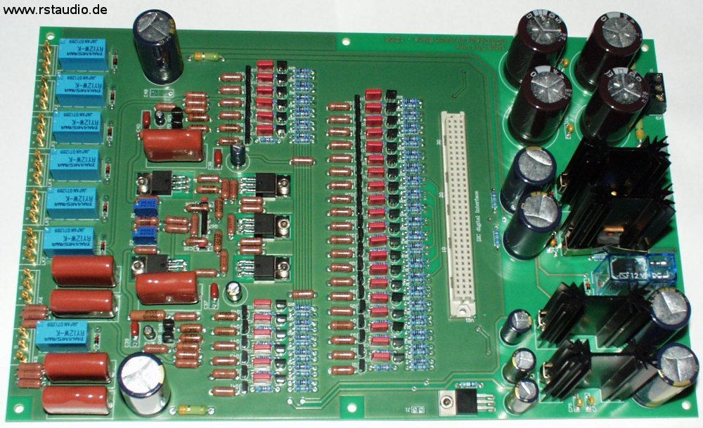
In my opinion, a major drawback of all NP’s mixed analog/digital circuits is the direct connection of the microcontroller system to the audio electronics, even though this apparently has no negative effect (see the very positive reviews). Since in the X0 design the volume is controlled via a series of bipolar transistors and this is done directly from the digital control, a connection between the analog and digital grounds is inevitable.
In my design, all control signals are transmitted via the I²C bus. This allows me to route the bus, which is floating, from the audio circuit to the control electronics of the volume bipolar transistors. This prevents a connection between the digital and analog grounds. Another advantage of the I²C bus is that its two signals (SDA and SCL) are static as long as nothing is being transmitted (there is no continuous clock signal). This means that switching edges only occur during switching (volume, relay), which, in my opinion, would be tolerable.
The circuit diagram clearly shows how I implemented the isolation from the microcontroller. The I²C bus signals and all externally required voltages are fed to the driver board via PF1. IC1 and IC2 are used to drive the relays on the X0 board. No explicit potential isolation is required here, as the relays already fulfill this function. IC4 connects the I²C bus to the preamplifier’s electronics in a potential-free manner. IC3, IC5, IC6, and IC7 directly drive the transistors for volume control. These ICs derive their operating voltage from the analog operating voltage of the X0 board. As long as nothing is switched, all control signals are static, so there is no risk of sound degradation caused by digital clock signals. The VG1 connector strip provides electrical and mechanical coupling between the digital I/O board and the preamplifier board. The address on the I²C bus is set using jumpers J1 and J2, allowing the board to operate for either the left or right channel.
I have also included a chip for temperature measurement, the IC8. This chip is mounted on only one of the two boards, as otherwise it would cause an address conflict on the I²C bus. Its purpose is to allow the internal temperature of the audio unit to be determined at any time. I assume that after a short period of operation, a stable internal temperature will be established in the unit due to the power dissipation of the low-power MOSFETs. However, to obtain a reading of this temperature, the measurement must be taken inside the closed enclosure. This is possible at any time during normal operation via IC8 by selecting a menu item on the control unit.
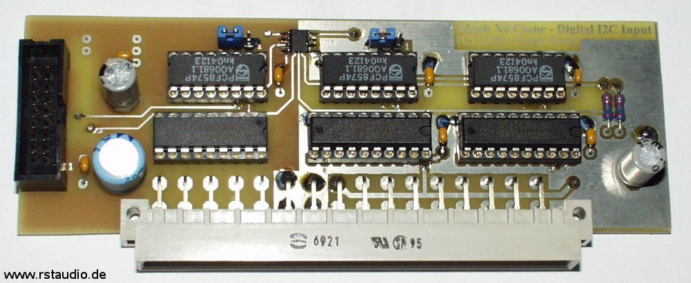
Finally, here are two photos of the Audio Unit with its case open. The two add-on boards for digital control are clearly visible in the photos. I once again used Van den Hul D101 cable for the internal wiring of the audio signals.
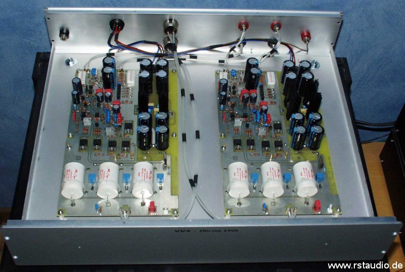
Phono Unit
August 19, 2007
The phono unit is my replica of the Pass Labs Xono. It is housed in the same enclosure as the audio and control units, and therefore forms a visual unit with both of them. The phono unit receives its unregulated power supply from the control unit.
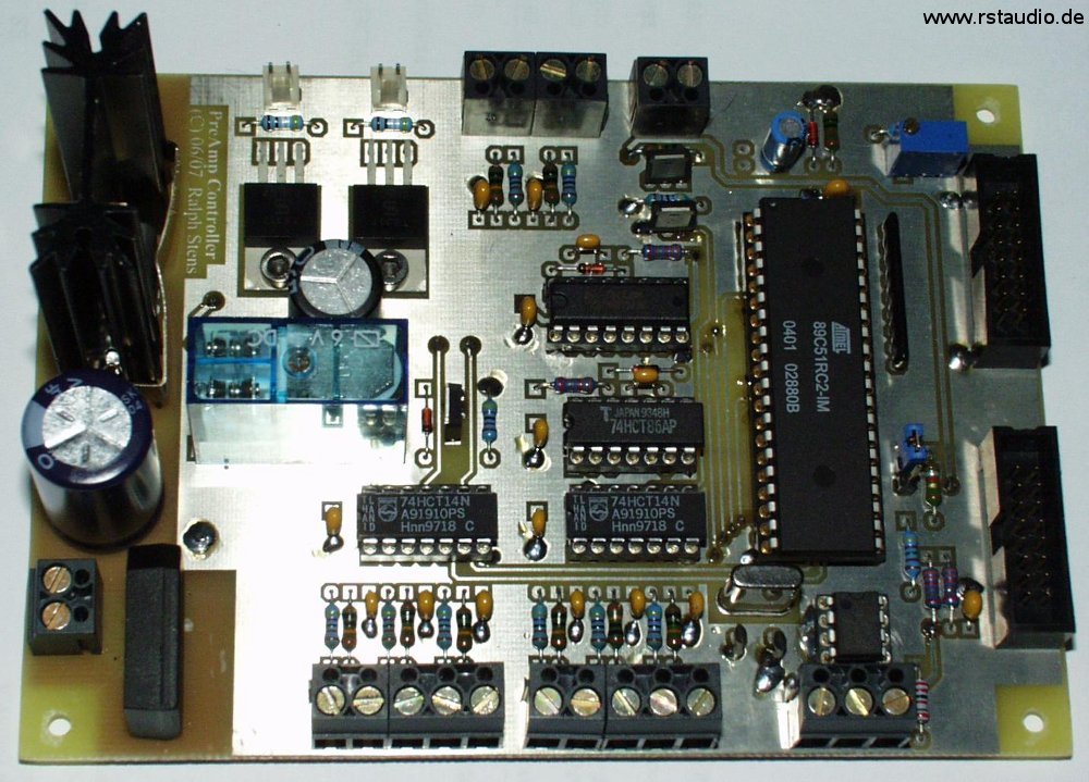
Control Unit
March 15, 2008
The control unit essentially consists of the following functional groups
- Microcontroller board for controlling and operating the preamplifier
- LCD display and rotary encoder as a user interface
- Passive power supplies for the phono and audio units
The μC board is based on the VV3 board. The software can control both preamplifiers and differs only in those parts where different hardware must be accessed. The preamplifier is selected via jumper J3.
- Schematic of the Controller
- Schematic of the Encoder Inputs
- Schematic of the Power Supply
For the microcontroller, I am once again using the well-proven Atmel AT89C51RC2 (IC1). All user-entered parameters are stored in the I²C bus EEPROM (IC2). The encoder signals and the two buttons that are normally unused are connected to the microcontroller via a debouncing circuit (RC low-pass filter and inverter). The rotary encoder for volume control triggers an interrupt on both rising and falling edges. IC9 prevents the volume signals from changing too rapidly, thereby preventing the encoder from being turned too quickly. Q2 and Q3 are used to generate the remote output signal for turning the power amplifiers on and off.
The software is based on the VV3’s code. I have revised it and removed features that proved ineffective during the VV3’s operation. However, the user interface has proven very effective — especially the interrupt-controlled volume adjustment — and has been fully retained.
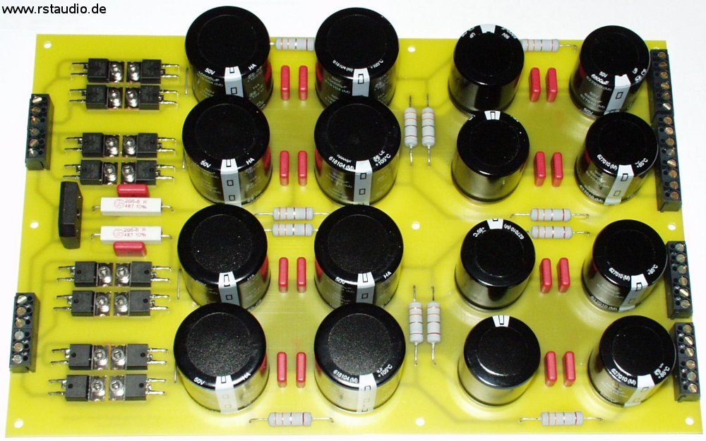
The passive power supply consists of rectification via an HFA08TB60 diode (ultrafast, soft recovery) and a combination of electrolytic capacitors and resistors. The total capacitance of both channels amounts to approximately 134,000μF. The power supply is, of course, strictly channel-isolated (dual-mono). The grounds of both channels are connected to earth on this board via 4.7Ω/5W resistors.
- Schematic of the passive Power Supply
- Schematic of the Capacitors per Channel
- Assembly of the Boards
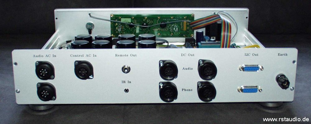
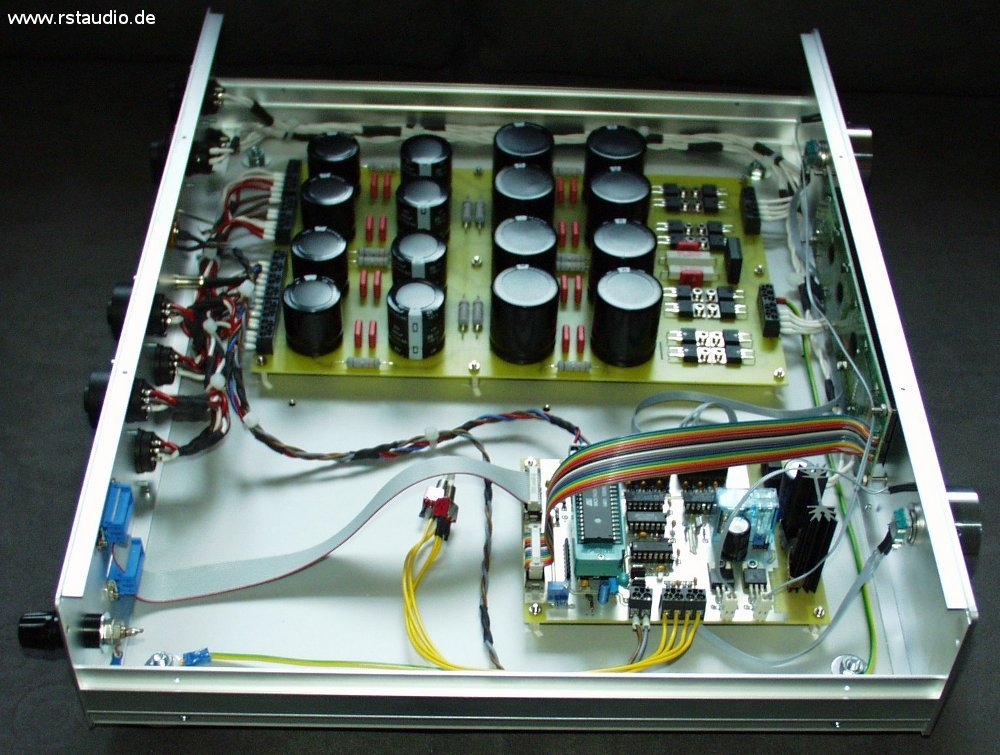
The next three photos show the control unit after it has been fully wired, still inside its open housing. The two beautiful control knobs were crafted by Enrico V. (see VV3) to his usual high standard. That is why I would like to take this opportunity to
a heartfelt thank you to Enrico V.
for his wonderful work.
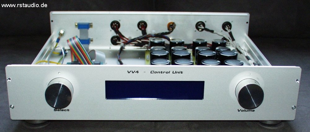
It is clear that the software development was not yet complete: The controller was mounted on a Textool socket, and the two loose buttons with yellow wiring were used for debugging during the development phase.
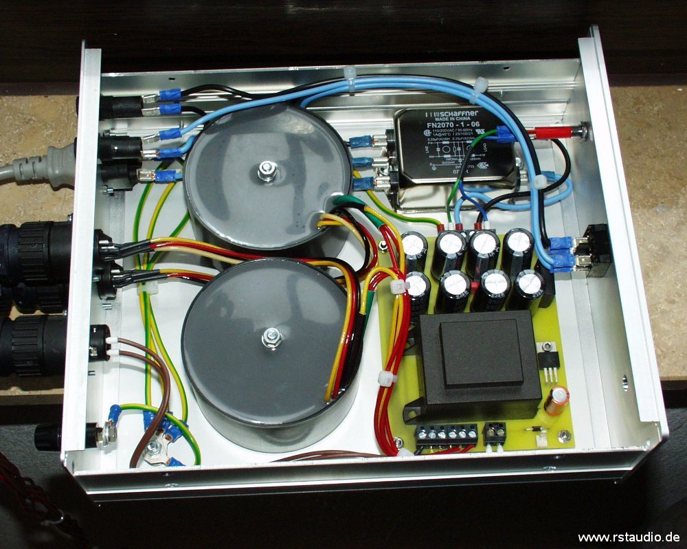
Power Unit
April 16, 2008
The Power Unit primarily houses the transformers required for the preamplifier. This module contains the entire 230V/AC wiring. Of course, DC filtering of the AC voltage and phase detection are also built in here. Unlike the DC filters in the VV3 and the Zen power amplifier, I have arranged the capacitors here in such a way that reverse polarity cannot occur. However, this comes at the cost of a significantly larger number of components (eight capacitors instead of two). As a mains filter, I have used a very sophisticated, two-stage 1A type from Schaffer this time.
- Schematic of the DC-Filters including the control unit’s transformer