Table of Contents
Introduction
November 23, 2017
My friend Heiner had been asking me for a long time to build him a multi-channel preamplifier. Since the project appealed to me greatly, I began development in the third quarter of 2016. First, I had to establish the basic concept for the hardware and software. I also wanted to incorporate as many of my current circuit topologies as possible into this preamplifier. Ultimately, however, I redesigned all the circuits and created new layouts.
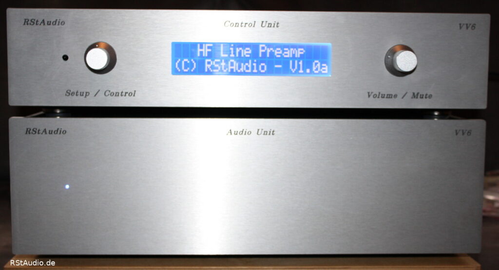
The entire preamplifier is housed in two enclosures
- The control unit consists of
- the 230V/AC input with mains filters
- the generation of unregulated analog voltages
- the generation of digital voltages
- the controller board for control and operation
- The Audio Unit consists of
- 2 motherboards, each for 6 expansion cards
- 12 expansion boards containing the actual preamplifiers
Control Unit
January 5, 2018
The control unit houses all circuit components that are not directly involved in audio signal processing. In particular, the mains voltage is supplied only to this part of the preamplifier.
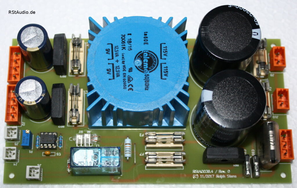
The 230V/AC power enters the enclosure via a mains filter with integrated fuses. This voltage is routed to the first circuit board via the power switch. On this board, there is first an additional capacitive filter, followed by a 230V/AC DC filter. Behind these filters are two external toroidal transformers for generating the audio voltages, as well as a toroidal transformer on the board for generating the digital supply voltages. All transformers are additionally protected by individual fuses. The digital voltages are rectified directly on this board. Two unregulated DC voltages are available: μC board supply and relay voltages.
This board also includes a circuit for determining the current phase angle. For the first time, I gave serious thought to the functional safety of such a circuit and redesigned it accordingly. I now use a glow lamp that can be switched between a phase and ground via a relay controlled by the microcontroller. Should a defect occur here, the likelihood of danger to the user is extremely low.
Of course, the user’s safety is primarily ensured by grounding the enclosure.
The neon lamp is monitored by a photoresistor, whose signal is connected to the microcontroller board via a comparator. When checking the phase angle, the controller closes the relay and evaluates the comparator’s output signal. The relay is then deactivated again.
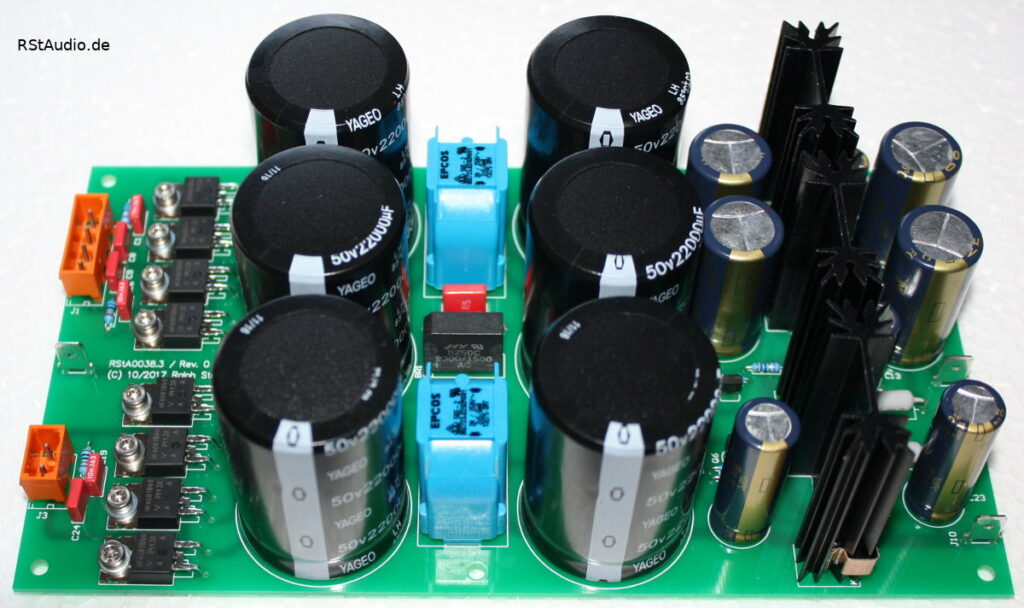
Two additional circuit boards in this unit are responsible for supplying the unregulated DC voltages to the audio circuitry. Here, I rely on proven technology. Snubber networks are located immediately behind the secondary windings of the toroidal transformers. These are followed by rectifiers with discrete ultra-fast soft-recovery diodes. Next comes CLC filtering with 22mF capacitors. Behind these filters are capacitance multipliers with additional low-pass filters leading to the output. From here, the DC voltages are fed into the audio unit via a cable.
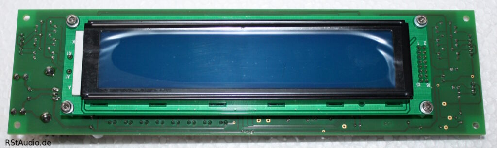
Another circuit board, housing the control microcontroller system along with the LCD display, is mounted behind the front panel. Here, I’m once again using my well-proven Atmel AT89C51ED2 x51 controller. Communication with the audio unit takes place exclusively via the I²C and SPI serial protocols and remains in standby mode as long as no switching occurs. The preamplifier is operated via two rotary encoders or an RC5 remote control, as well as the display with two rows and 20 columns.
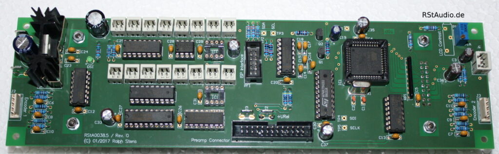
The LC display has two rows and 20 columns, with a character height of 12.7 mm. As mentioned above, it is screwed directly onto the back of the microcontroller board.
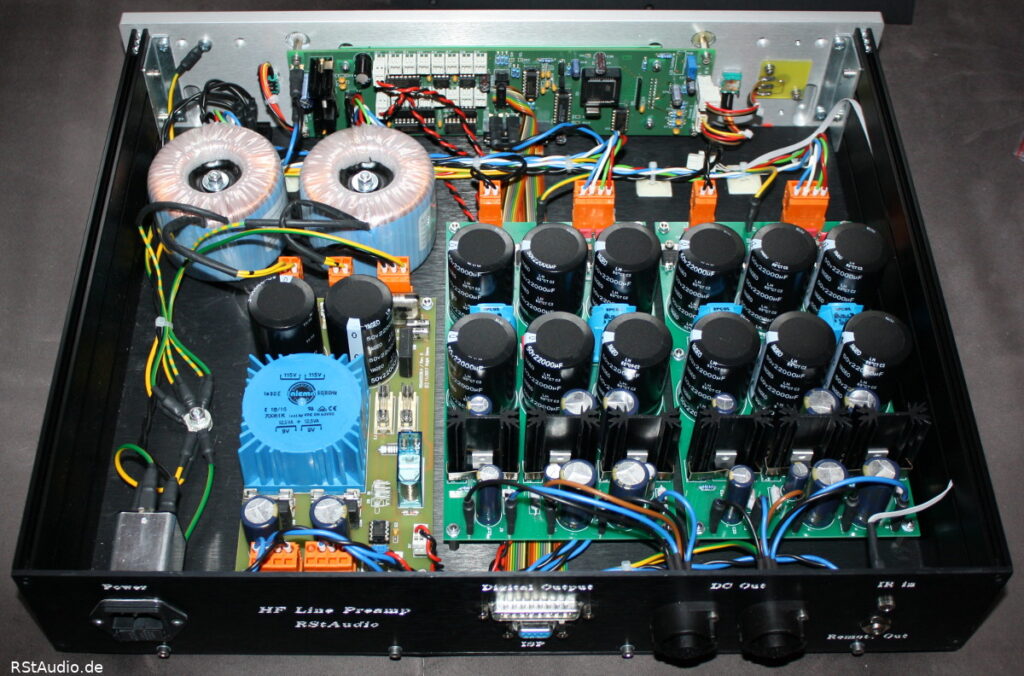
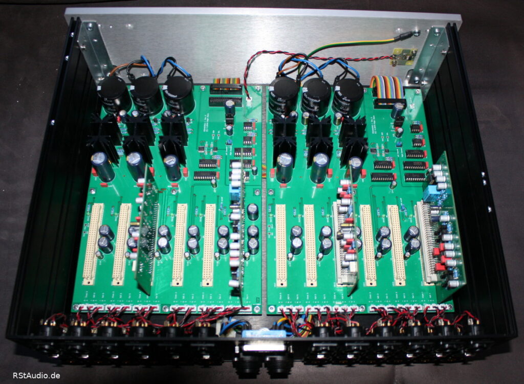
The following photo shows the complete control unit with the cover removed. All of the circuit boards and components described above are clearly visible.
Audio Unit
January 22, 2018
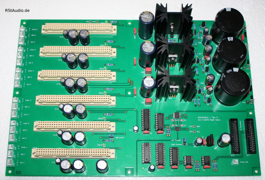
The Audio Unit is almost entirely filled by two bus boards. These boards feature discrete voltage regulators for powering the analog circuits, as well as six slots for audio boards. For each of these six slots, two inputs and one output are routed directly to the board. This eliminates the need for any wiring to the audio boards.
Each bus board also features a digital circuitry section for controlling the relays and digital potentiometers. The transition from the microcontroller system to the analog circuitry is achieved through electrical isolation using components from Analog Devices’ ADuM series.
There are two types of audio boards. Both have identical circuit topologies. The balanced input is connected directly to the first amplifier stage, while the unbalanced input is first balanced using a DRV134/135. The balanced signals are then fed to the amplifier, which consists of an OPA1632. The gain is set to 6dB. After this amplifier, the balanced signal is adjusted to its final volume using a digital potentiometer, which utilizes the MUSES72320. The final stage consists of a balanced output driver.
The two boards differ in their output circuitry. The first board is equipped with two operational amplifiers connected in parallel for each signal phase (2 × OPA1612).
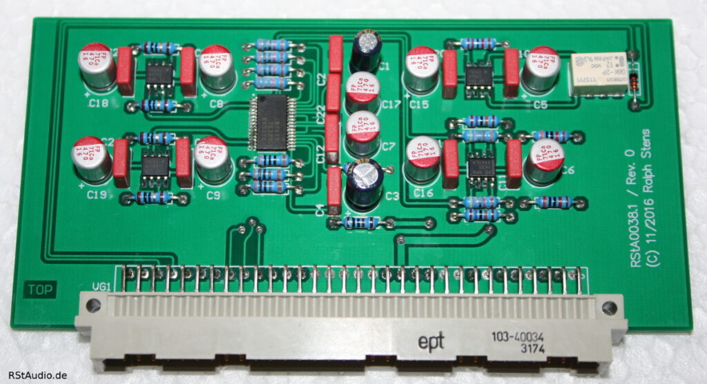
The second board, on the other hand, features discrete diamond buffers with servo controllers. The OPA1632 and MUSES72320 are mounted on the back of the board.

The bottom image shows the entire audio unit from the back with the cover removed. A total of four audio cards are installed.
Installation in the Enclosures
January 22, 2018
As has been my practice in recent years — with the exception of the active absorber — I used enclosures from HiFi-2000. For the control unit, I’m using an enclosure with an internal height of 80mm, and for the audio unit, one with a height of 120mm. I need the taller enclosure to make room on the rear panel for all the connectors. In addition, the plug-in cards naturally also require some vertical space.
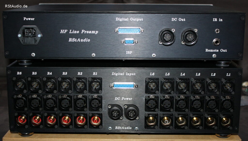
The front view is shown at the top of the page. The LCD screen is positioned in the center. To the left and right of it are the two rotary encoders. On the left side, you can see the built-in IR receiver.
The rear view can be seen in the photo below. For each channel, the two inputs (XLR and RCA) and an XLR output are visible. The 25-pin Sub-D connector transmits the digital signals and the digital power supply from the Control Unit to the Audio Unit. The Hirschmann industrial connectors are used to connect the analog signals between the two enclosures. The two connection cables required for this are custom-made.
The control unit features a 9-pin Sub-D socket for transferring software to the microcontroller (ISP – In-System Programming), an input for an external infrared (IR) receiver, and an output for the remote power supply (see above). Of course, there is also an input for 230V mains voltage with a filter and integrated fuses. The power switch is not visible in the photos. It is located on the front right side of the bottom of the control unit.
Audiophile Review
January 22, 2018
So how do these two audio modules compare to the VV5? I have to say: surprisingly well! That said, I’ve only listened to them for one afternoon, so the preamp modules haven’t had a chance to break in yet. My friend Heiner will run them for a while first, and then we’ll both share our thoughts.
April 3, 2018 / Ralph :
My initial positive impression did not mislead me: At this point, I would find it difficult to choose between this preamp and the VV5. The level of detail in both preamps is comparable, though there are slight tonal differences. However, these come down to personal preference, so I couldn’t say which one I would ultimately choose. All in all, a rather successful design that demonstrates what modern audio ICs are capable of today.
April 23, 2018 / Heiner :
Now that I’ve owned the VV6 for some time and have listened to it for many hours, here are my impressions: In theory, all preamps should sound the same or very similar — that’s what the measurement data suggests. Everything is excellent, and any deviations are so minute that our ears can’t detect them. Yes, but that’s not how it is. The VV6 takes 1–2 hours to warm up. After that, it plays in a way that makes me want to listen to music. I listen to CDs from start to finish and no longer just play my “test music.” Complex structures (e.g., tutti in classical music) are so clearly separated that they no longer seem complex at all. Or rather, it must be child’s play to resolve them and present them as musical events. The VV6 can make every instrument sound natural, just as it does with small ensembles. The spatiality is very convincing. It’s truly enjoyable, and listening to music is beautiful, musical, and effortless. I’ve treated my living room acoustically quite well, and the reverberation times are reasonably linear across the frequency response. The VV6 is now running in this environment and continues to bring me joy every time I listen.
It should also be noted that both of us — and quite independently of one another — prefer the module with the Diamond Buffer.