Table of Contents
Introduction
February 22, 2010
In February 2010, during the ACT-Niederrhein get-together, the idea arose to build our own Hiraga MC Prepre. I had always been interested in this preamp, so it didn’t take much convincing for me to start working on a design. Since the circuit is very simple, the PCB was quickly designed.
Circuit of the Hiraga MC Stage
October 24, 2021
To describe the circuit, I would first like to show Jean Hiraga’s original circuit from the magazine L’Audiophile.
The transistors used in the original circuit are now very difficult to find, which is why some alternatives are recommended online, such as the TBC560 from Toshiba. However, according to a long-time user of this circuit, the BC560C is not the best choice. He recommends the 2SA1038 or 2SA1085, which are also PNP transistors from Toshiba. Since I had enough 2SA1085s in stock, I chose this transistor.
The output capacitor should be a very high-quality audio coupling capacitor. For this reason, I chose a Mundorf MCap Supreme Silver/Gold for this application. For resistors, I used the proven, non-magnetic Vishay-Dale CMF-55-143 resistors and Panasonic FC electrolytic capacitors rated for the operating voltages.
- Schematic diagram of my Hiraga MC pre-preamp
- Board Assembly
From a batch of 50 transistors, I identified two pairs that were nearly identical by measuring their current gain. I then thermally coupled the pairs on the circuit board, as shown in the photo above. To do this, I applied a thin layer of thermal paste to the end face of one transistor and then connected both with a piece of heat-shrink tubing. During an initial quick check using a lab power supply as the voltage source, I was able to adjust both inputs to within a few µV using an Agilent benchtop multimeter.
Operating Power Supply
October 24, 2021
Most users of the Hiraga Prepre use batteries for power. I didn’t want to go that route at first, so I opted for a shunt regulator instead. This is the first time I’ve used a voltage regulator like this in my circuits, so my experience with how such a regulator behaves was limited to Spice simulation.
For the design, I largely followed the circuit proposal below:
- Shunt or Not
Are Waagbø
audioXpress, 02/08
I wanted to use a simple and completely discrete regulator, so I chose the Simple Shunt Regulator with Constant Current Source.
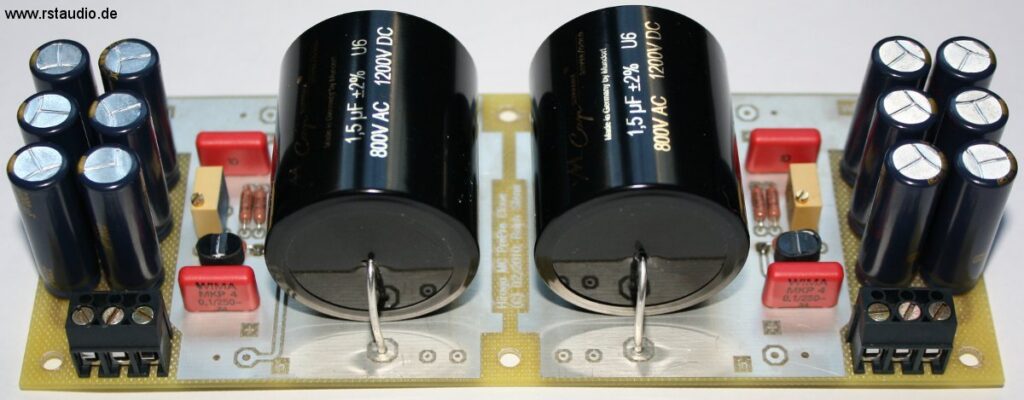
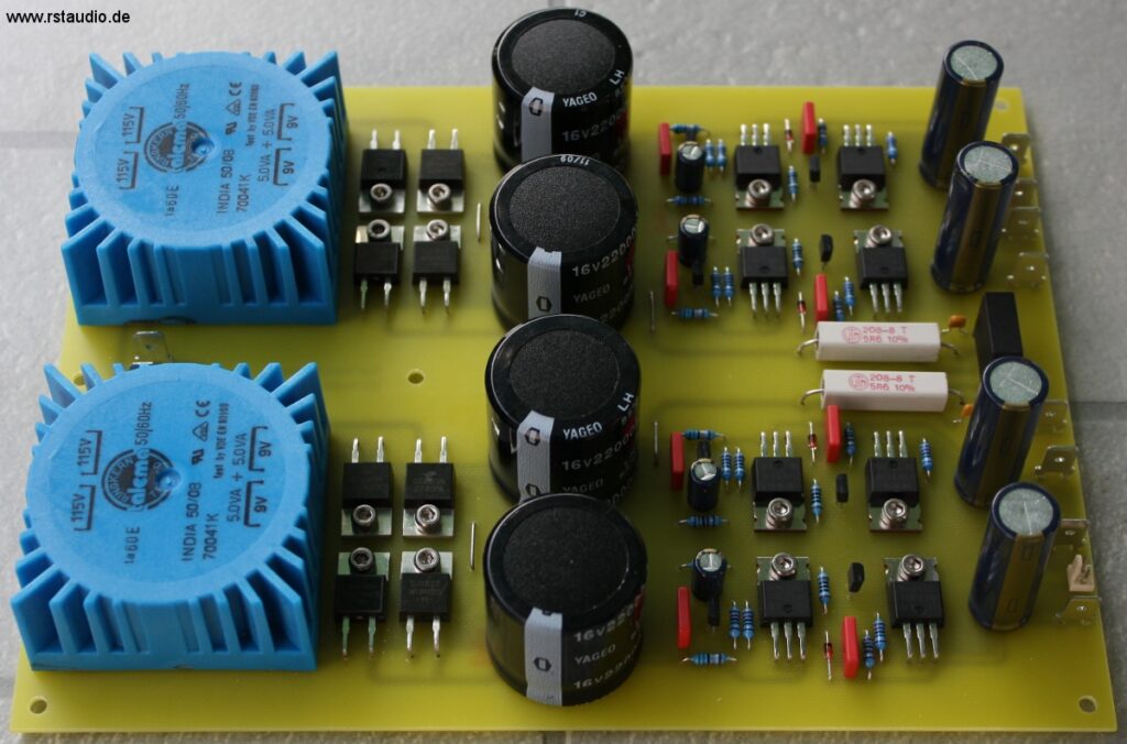
As always, the power supply is designed in a dual-mono configuration. Following the transformer, the rectifiers (built using discrete components with ultrafast soft-recovery diodes), and the first filter capacitors (4× 22,000µF), the circuit includes current sources rated for approximately 10mA. The Hiraga MC draws approximately 1mA from the positive supply voltage and approximately 2mA from the negative supply voltage. Thus, the current sources are well above the design recommendations for a shunt regulator, namely twice the current of the load.
3300µF Panasonic FC electrolytic capacitors are installed at the output of the regulators. Inside the MC stage’s enclosure, there are also four 100,000µF electrolytic capacitors, supplemented by 10µF Wima MKP4 capacitors. The Hiraga MC’s circuit board itself houses another twelve 2200µF Panasonic FC electrolytic capacitors. The total capacitance behind the regulators thus amounts to a nominal 439,640µF. This may not quite meet J. Hiraga’s expectations, but it is more than sufficient for an initial setup. Additionally, the shunt regulator is housed in a separate enclosure and could therefore easily be replaced by batteries.
A key factor in my decision against using batteries was my experience with the Pass Labs XOno. This phono preamplifier takes a very long time to reach a stable operating point. That’s why I never turn it off, just like with the Hiraga MC. Since power consumption is very low, it’s best to simply leave the amplifier running, which requires a power supply.
Installation in the Enclosures
07. Mai 2010
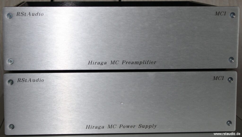
As mentioned above, the entire Hiraga-MC preamplifier is housed in two enclosures for audio and power supply. The enclosures are from HiFi 2000. From their product range, I chose the Galaxy Maggiorato, which measures 330mm × 280mm × 80mm (W × D × H) and has a 10mm thick front panel.
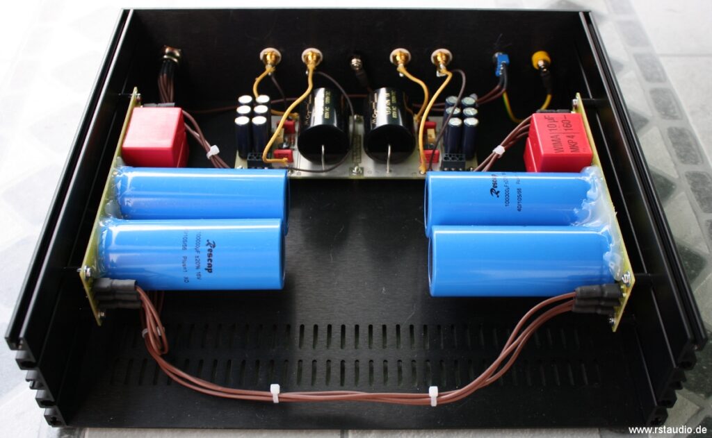
The photo below shows the audio chassis from the front; the front panel has not yet been installed. The circuit boards with the 100mF electrolytic capacitors and the 10µF MKP4 capacitors are mounted on the two side panels. The pre-preamp itself is located in front of the rear panel.
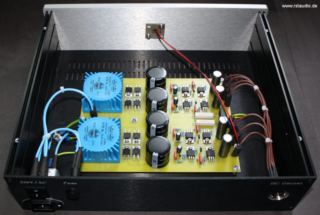
The enclosure with the shunt regulator is shown below.
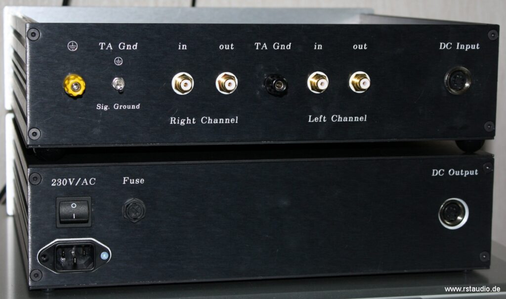
On the back of the preamplifier are the RCA inputs and outputs, the connection for the tonearm/turntable ground cable, a ground terminal, and a 7-pin DIN connector for the power supply. Using the switch on the left side, the ground cable connection can be connected either to the power supply ground or to the external ground.
The power supply unit’s housing naturally features an input jack for the 230V/AC power supply, as well as a power switch and a fuse. On the right side is a seven-pin DIN connector through which the operating voltage is output.