
Introduction
July 29, 2026
In June 2026, I received a question about the best way to convert the output signal from an XOno into a mono signal. The reason for this question was the occasional playback of mono records using a stereo cartridge.
The idea is that I have a small collection of reissued mono records (~20) and only a stereo cartridge.
I would like to have it so the phono stage outputs the same signal per channel whether through summing or something similar so the output is exactly the same.
Right now the outputs are pretty close but not exact.
We discussed the various options for implementing the task a little more. Afterward, I set to work on developing and building the Stereo Mono Converter (SMC).
Circuit Description
July 29, 2026
The balanced output signals from an XOno or another signal source are connected to the two inputs of the SMC. In normal stereo mode, these signals are routed directly and passively via relays to the SMC’s outputs. This is also the default position of the relays when the SMC is turned off. Therefore, when listening to stereo, the SMC can remain turned off.
When the SMC is turned on and mono mode is enabled, the left and right channel signals are routed to a balanced summing amplifier. The outstanding balanced operational amplifier OPA1632 is used for this purpose. Since a summing amplifier inverts the phase, a second stage with two inverters follows to correct the phase again.
In the second stage, I use the OPA1656 dual operational amplifier, which has extremely low noise. This allows me to keep the balanced output signal free of offset voltages using a servo controller for each signal. For this, I use two OPA197s.
The balanced output signal from this stage is then routed to the output jacks of both channels. There is one XLR jack and one RCA jack per channel. The unbalanced RCA jacks are simply connected in parallel to the balanced output signals, as is already the case with the XOno.
The total gain of the active stage is, of course, set to 0dB.
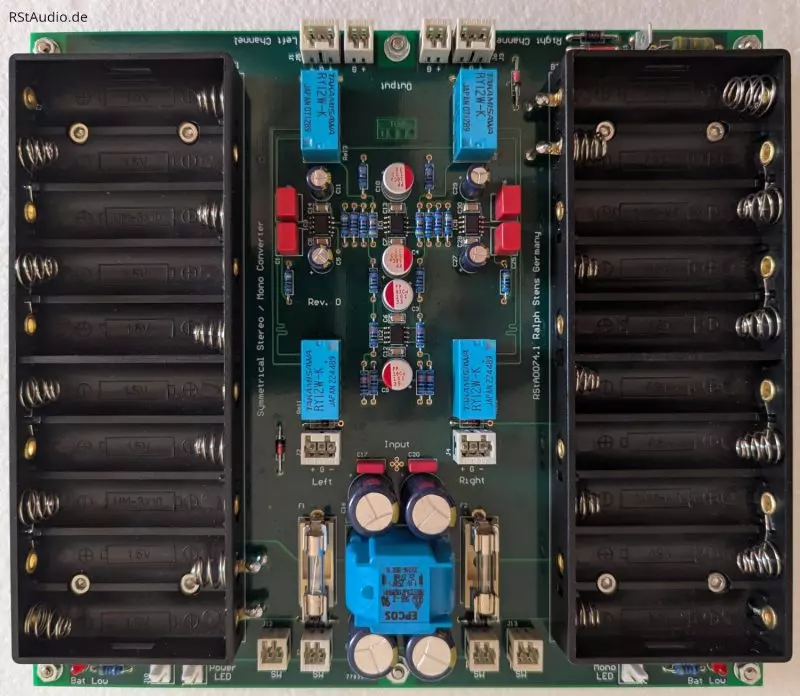
Since the SMC is only used occasionally, we decided to power it with batteries. To achieve a ±15V supply, I used 2 sets of 10 AA batteries. These should provide more than enough power to keep the SMC running for quite some time.
Although batteries are used in the power supply, a CLC filter is employed. The large electrolytic capacitors, together with the smaller ones placed directly on the op-amps, provide sufficient current to respond even to extreme voltage spikes in a highly dynamic music signal.
Each battery pack has a circuit that monitors the ten batteries for undervoltage. The circuit board contains a fault LED for each battery pack, which lights up in the event of undervoltage. In addition, there is an LED on the front panel that turns on as soon as at least one of the packs experiences undervoltage.
Installation in an Enclosure
August 12, 2026
As usual, I used an unmodified chassis from Italy. Since this is a smaller unit, I was able to use a Galaxy Maggiorato. Unfortunately, the current-compensated dual choke prevented me from using a 1U chassis.
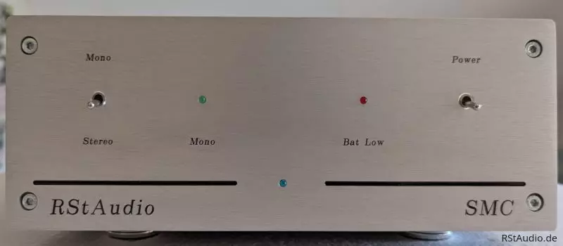
At the top of the page is a photo of the SMC’s front panel. It shows two toggle switches and three LEDs. The right switch turns the unit’s power on and off. When the power is on, the blue power LED in the center, between the two lines, lights up. The left switch allows you to toggle between stereo and mono modes. In mono mode, the green LED next to the left switch lights up. Stereo mode with the power supply turned on is used to warm up the electronics. Next to the right switch is also a red LED that lights up if the voltage of at least one of the two battery packs is too low.
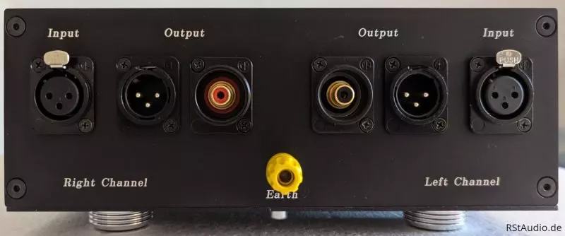
On the rear panel, you can see the two XLR inputs on the far left and right. In the center are the outputs, each equipped with XLR and RCA jacks. I positioned the RCA jacks in the center so that a stereo RCA cable could be connected without any problems. The yellow 4-mm lab jack can be connected to earth (ground-earth connection), though this wasn’t necessary during a test run on my system.
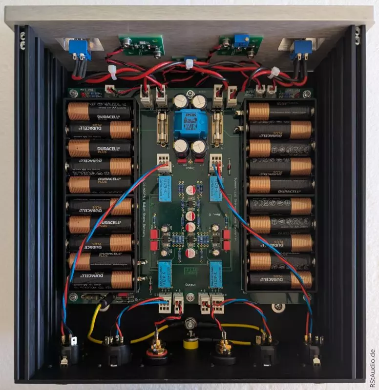
The photo above shows the interior of the SMC. I deliberately adjusted the size of the circuit board to fit the enclosure I used. That’s why everything fits together perfectly.