Table of Contents
Introduction
March 24, 2012
Even though I was very satisfied with the sound of my VV4 preamplifier (X0.2 and XOno), I had been thinking about building a new one for quite some time. In particular, the decision to distribute the components across multiple enclosures and to incorporate a new control system with additional expansion options led me to this decision in 2011.
Right in the middle of the project — the X0.2 circuit boards had already been assembled — I received the schematics for the newer XP-10 and XP-20 preamplifiers from Pass Labs. Naturally, I revised my plans and replaced the X0.2 line preamp with the XP-20.
Shortly before assembling the XP-20 board, I had gathered so much information about the differences between the XP-20 and the XP-30 that I was able to build a replica of the XP-30 without having its schematics.
Based on the experience and insights gained over the past few years, the following design for the VV5 preamplifier has been developed:
- Preamplifier distributed across 3 enclosures
- Left and right audio channels, each in its own housing
- A channel consists of an XP-30 and an XOno replica
- Additional board with relay switches for the inputs and outputs
- All inputs and outputs feature balanced and unbalanced connectors
- Additional enclosure with microcontroller-based control and dual-mono power supply
- Line Stage with an XP-30 replica
- XP-30 Line Stage, including the unbalanced output stage
- No input switching on the board
- Operating voltage controls via plug-in modules
- Space for various coupling capacitors at the output
- Phono preamp with an XOno replica
- Most of the DIP switches in the XOno have been replaced with relays
- Additional input via a second MC stage
- Operating voltage control via a plug-in module
- Space for various coupling capacitors at the output
On May 9, 2013, the VV5 took the place of my VV4.
I had expected an improvement in sound quality from the X0.2 to the XP-30. The X0.2 is undoubtedly a truly excellent preamp, and I’ve enjoyed listening to music with it for several years. But I hadn’t anticipated that the differences would ultimately be so pronounced. The XP-30’s resolution and richness of detail are simply indescribable. The XOno also benefits more than expected from the new power supply and coupling capacitors. All in all, a huge success that I’m more than satisfied with.
On October 3, 2013, I replaced the volume boards with the Maxim DS1882 chip with boards featuring the NJR MUSES72320 chip. I now fully understand Wayne Colburn’s decision to use these chips in the XP-30 and highly recommend these digital potentiometers to any DIY enthusiast. The improvements are more than obvious.
Control Unit
March 24, 2012
This module is used to power and control the audio units. It is the only module in the preamplifier that comes into contact with 230V/AC and consists of the following components:
- 230V/AC mains input with mains filtering
- Detection of the correct phase
- 2 transformers for powering the audio units
- Power supply for the audio units
- Transformer and power supply unit for powering the control system
- Microcontroller board for controlling the preamplifier
The user interface once again consists of two rotary encoders and an LC display. In addition, this time the preamplifier comes with a remote control that allows all essential settings to be adjusted directly from the listening position. The software is, of course, based on that of the VV3 and VV4.
Control
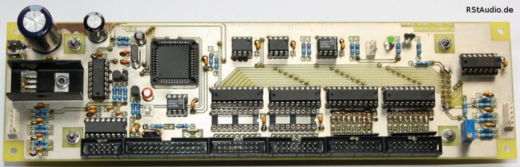
In this project, the microcontroller board forms a single unit with the display and is mounted directly behind the front panel. As with my other projects, I am once again using a controller from Atmel’s x51 family. However, this time I am using the AT89C51ED2 in a PLCC44 package. This chip offers 64 KB of program memory and, most importantly, the ability to perform in-system programming (ISP) via a bootloader over the serial interface. This allows me to make changes to the software even after the device has been fully assembled, without having to go through the hassle of disassembling it.
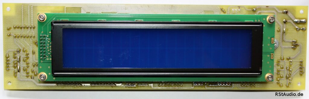
As described above, the user interface consists of two rotary encoders from Alps and a 2×20 LC display from Electronic Assembly with 12.7 mm digits, the same type used in the VV3 and VV4. There is also a pushbutton that can be used to turn the preamplifier — more specifically, the µC board including the power supply — on and off.
Communication with the audio units takes place exclusively via an I2C bus with full electrical isolation between the circuits. Also connected to this bus on the µC board are a 64-kbit EEPROM and a temperature sensor chip, which can be used to measure the internal temperature of the enclosure. An exception is the SPI bus for the MUSES72320 (see below), which also features electrical isolation from the audio circuit.
A unique feature of the µC board is that it includes a second I2C bus that is completely independent of the first. This is intended for future external expansions.
Unlike my previous designs, this board also allows you to connect up to 16 buttons, 12 LEDs, and 4 relays. This makes it possible to implement additional or alternative control options independent of the rotary encoders (mainly for you, Hans).
I use some of the LED outputs to control external optocouplers located in my motor driver. This allows me to inform the motor driver of the currently selected pickup — that is, a number between 1 and 5 — provided that one of the three phono inputs (see below) is active. Of course, both devices — the VV5 and the motor driver — must be configured with the same settings.
As with my other two preamplifiers, an IR receiver of the TSOP1736 type is integrated into the system. Unlike with the previous models, however, I have also included a remote control in the control scheme — that is, the software — this time. There are three buttons on the remote control for each of the two rotary encoders (left, right, and Enter), so only a minor modification to a large part of the software was necessary.
Power Supply for the Control System
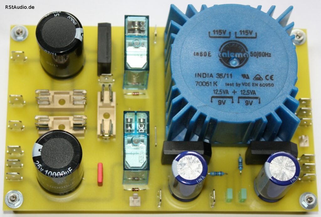
The board begins with a 230V/AC DC filter designed to eliminate DC voltages from the primary windings of the transformers. The transformer for the analog power supply (mounted externally) and the transformer for the control unit (mounted on the board) are each connected to this filter via their own fuse.
The transformer used for the control circuit is a 25VA toroidal transformer with two 9V secondary windings. A rectifier and an electrolytic capacitor are connected to each of the two windings. The board thus provides two unregulated DC voltages. One voltage powers the microcontroller, while the other powers the relays. The latter is also used as a remote control voltage.
The two relays are used to turn the power supply on and off. The controller is turned on using REL1 and an external pushbutton connected in parallel. REL2 can be used to turn off the power from the controller. Capacitor C8 ensures that the relay is held open for a short time, thereby guaranteeing a safe shutdown — after all, the same pushbutton is used as for switching on, only this time as a control command to the microcontroller.
Power Supply for Audio Units
The control unit also generates the DC voltage for the audio units. This is, of course, a dual-mono power supply, with one power supply per channel. With the exception of the transformers, however, both power supplies are mounted on a single circuit board. The only common reference point for both power supplies is the connection of the right and left grounds to earth via a resistor and two diodes connected in anti-parallel.
The power supply consists of a discrete rectifier with ultra-fast soft-recovery diodes from International Rectifier (HFA08TB60) and a CRC filter comprising four 10,000µF electrolytic capacitors and two 3.3Ω/2W resistors. This is followed by capacitance multipliers using low-power bipolar transistors. The DC voltages for the phono and line stages are decoupled via an RC filter (2× 1Ω/2W and 2× 2200µF) located downstream of these stages.
Since part of this circuit can also be found in the original XP-20 schematics, I will refrain from publishing my schematics here.
230 V AC Power Supply for the Preamplifier
The power socket with a switch and fuse is located on the back of the control unit. This is where the preamplifier is completely powered down. Normally, the switch is turned on, so that the analog circuits are active.
The socket is followed by a circuit that detects the correct phase alignment of the power plug, then a 3A mains filter, and finally the circuit board containing the DC filter and the power supply for the digital circuits (see above). The primary windings of the two 125VA toroidal transformers, which supply the analog voltage, are also connected to this circuit board.
The correct phase position of the mains plug is not detected automatically. I checked the wiring of the toroidal transformers for consistency, determined the phase positions of the primary and secondary sides, and connected them accordingly. I then measured the voltage between the analog grounds and earth, of course before the ground/earth connection was made. The circuit for detecting the phase angle is wired to send a signal to the microcontroller if the power plug is inserted incorrectly — that is, if a higher voltage is measured between ground and earth. The software then reports this.
Preamplifier Remote Control
With my last two preamps, I had planned to include a remote control but never got around to it. With the VV5, however, the remote control was an integral part of my specifications.
I have implemented an RC5-based remote control using the SAA3010 transmitter module and the TSOP1736 receiver. The receiver is connected directly to pin J1 of the microcontroller (see above). I have implemented nine buttons with different functions.
| Volume – | Mute | Volume + |
| Select Left | Enter | Select Right |
| Power Off | Reserve 1 | Reserve 2 |
Ultimately, I reproduced the function of the rotary encoders using the buttons on the remote control. This greatly simplified the integration of the remote control functions into the preamplifier’s software.
The remote control transmits the standard RC5 address for preamplifiers (16). The “Volume” and “Mute” functions are also standard in a preamplifier’s command set. The other functions are assigned to free commands. This means that a commercial remote control for preamplifiers, such as the remote control for my CD player, which has a corresponding function, can also be used to adjust the volume.
Audio Unit
March 28, 2012
This module contains one channel of audio circuitry, which is why two of them are required for a stereo preamplifier. An audio unit consists of the following components:
- Replica of an XP-30 line preamp
- Replica of a UGS6 module as the basis for the line preamp
- XOno replica with various modifications and improvements
- Additional second XOno MC input
- CLC Filtering of the DC Voltage
- Voltage Regulator Modules for Line and Phono
- Relay board for switching inputs and outputs
- I2C bus board for controlling the respective audio unit
XP-30 Replica
I have the schematics for the first version of the XP-20, which uses the Maxim DS1802 digital potentiometer. After thoroughly studying these schematics, reading test reports on the XP-30, examining photos of the preamplifier’s interior, and reviewing various comments in the forums, I had gathered enough information to begin building a replica of the XP-30.
The XP-30’s audio circuitry differs from that of the XP-20 in several key ways; however, the core of the circuitry — the UGS6 module — is the same in both preamplifiers. The XP-30 primarily uses a different chip for volume control and features an additional buffer at the output.
The unregulated power supply has remained essentially the same, but the XP-30 has two transformers, as is my standard practice anyway. It is therefore a true dual-mono design, which also applies to the construction of the three enclosures.
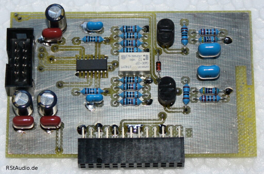
When construction began, the MUSES72320 volume chip was not available in small quantities to individual buyers, so I started with the chip from the second series of the XP-20 (Maxim DS1882). However, to make replacement easy, the entire volume circuit is mounted on a plug-in board.
The dynamic range of the DS1882 is 63dB, whereas that of the XP-20 preamp is 83dB. This is achieved by engaging a 20dB attenuator. This voltage divider is located directly after the board’s input and drastically changes the input impedance depending on its position. To avoid this, I decided to insert an additional bipolar B1 buffer directly after the input, before the attenuator and the volume chip. This results in a constant input resistance and a control range of over 80 dB with the Maxim chip.
With the MUSES72320, such an effort is unnecessary. The chip offers over 100dB of attenuation at a resistance of 20kΩ. This means you can connect this chip directly to the preamplifier’s input — without any additional buffer or attenuator — and still achieve an acceptable and largely constant input impedance.
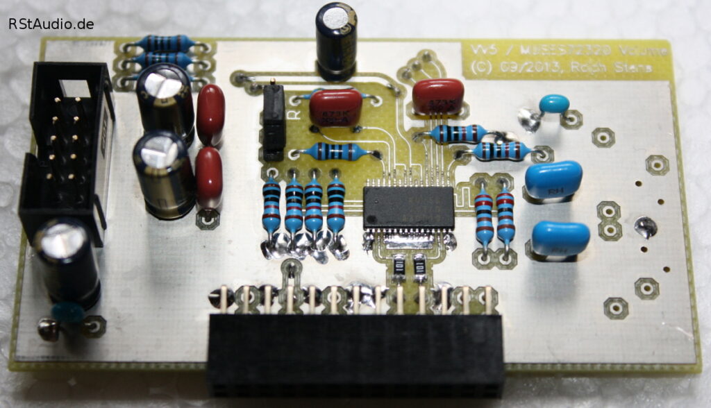
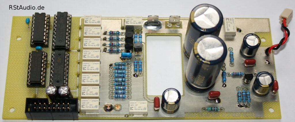
The MUSES72320 datasheet lists a minimum total resistance of 13kΩ and a typical value of 20kΩ. Since these are significant deviations, I have included an additional resistor network to compensate for any differences between the channels. The photo at the top right shows the unassembled section. Of the ten chips I own, I selected two and soldered them randomly into the circuits. I measured a deviation of 0.008dB in the total gain of the line stage in the range most important to me, down to −40dB, between the two channels. This, of course, makes the compensation completely unnecessary.
The DS1882 is controlled digitally via the I2C bus, while the MUSES72320 is controlled via the SPI bus. As usual, I wired both serial buses to the controlling microcontroller with electrical isolation.
I’m using a UGS6 module as the active circuit. Like in the original, I’ve mounted it on a separate circuit board. However, my dimensions are slightly larger, and I’m using through-hole resistors. Another small change from the original is that I’m using 10-turn trimmers throughout.
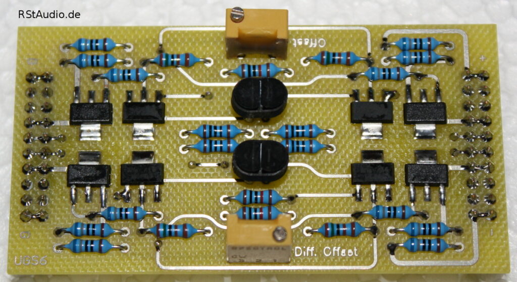
The XP-30 buffer features low-power MOSFETs at the outputs of the UGS6 module. Behind these buffers are only coupling capacitors, which decouple the UGS module’s inherent offset from the preamplifier’s output. Unlike the XP-20, which uses Panasonic FC electrolytic capacitors and ECQ capacitors, the XP-30 employs 10µF MKP film capacitors labeled Pass Labs. I use Obbligato Gold Premium capacitors in this configuration.
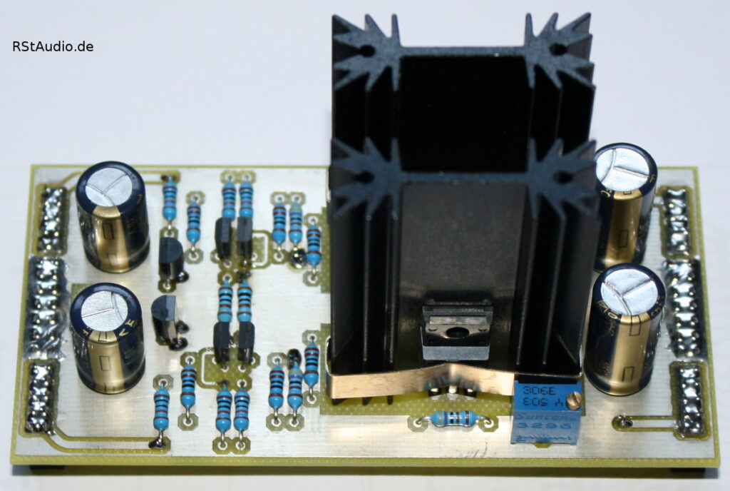
I have moved the XP-30’s active discrete voltage regulation to a separate circuit board similar to that of the UGS module. This allows me to use different regulation schemes simply by swapping out this circuit board. Unlike the original design, which uses standard voltage regulators, I also use these discrete regulators to supply the analog voltages for the digital potentiometer. The digital supply is generated by an integrated regulator from Linear Technology.
The schematics will not be published here.
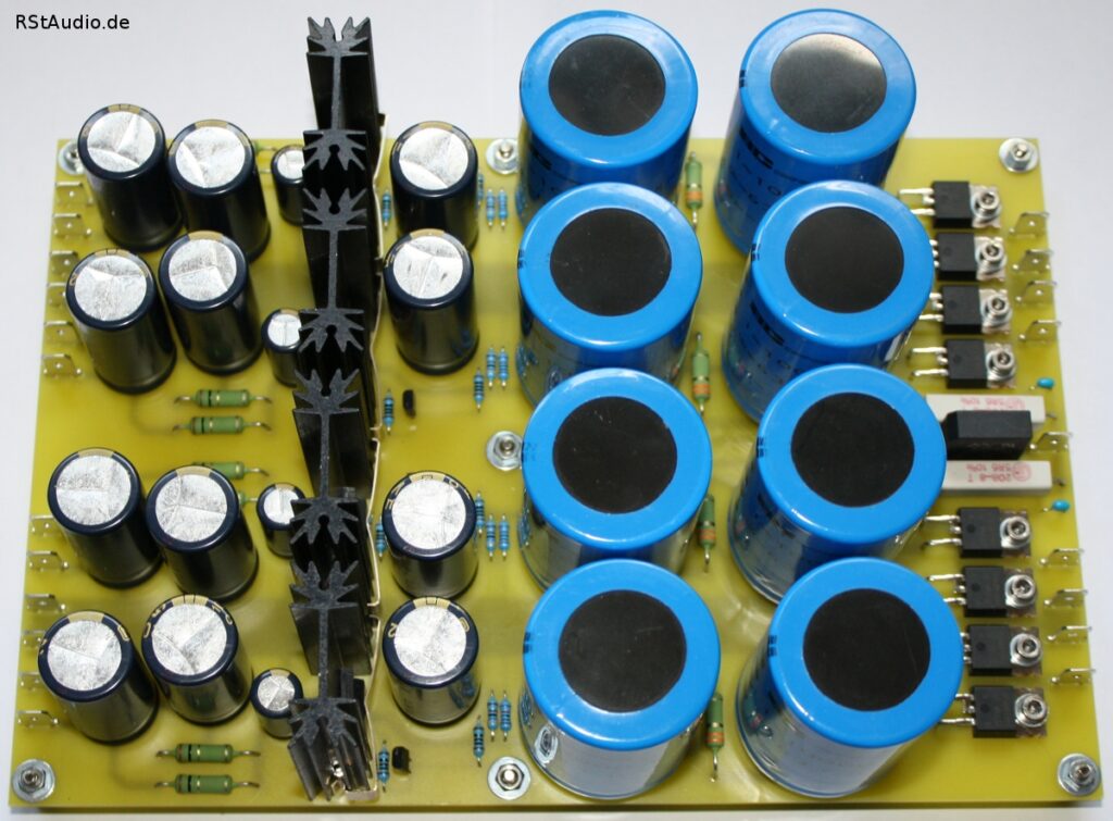
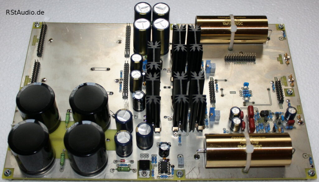
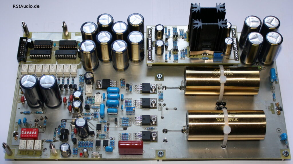
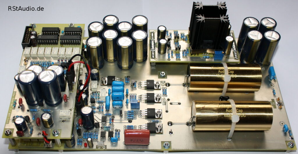
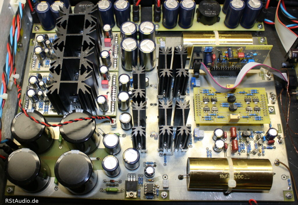
Finally, here is a photo of the complete XP-30 replica, including all the add-on boards (see below). At the bottom left is the DC voltage input with CRC filtering. Above it are the two boards for voltage regulation of the analog voltages for the UGS6, buffer, and SE output stage, as well as the regulator for the analog power supply to the digital potentiometer (DS1882 or MUSES72320). In the center bottom is a circuit that ensures the analog voltage is applied to the digital potentiometer rather than the digital signal. This is very important for interference-free operation of the DS1882. Directly above it is the digital power supply. In the center right is the UGS6 board, and to its left are the output buffers. Below that, you can see the discrete operational amplifier for the single-ended output. At the top is the board with the potentiometer (here, the DS1882 board). The two output coupling capacitors are visible at the top left and bottom right. There is still room for slightly larger types (e.g., Mundorf).
XOno Replica
Of course, the XOno is based on the work and experience I’ve gained over the years with my XOno replica. Since my turntable now has two tonearms, I need to include two MC inputs in the preamp. I decided to mount the circuitry for the XOno’s MC input on a second circuit board above the main circuit board in order to create a second MC input.
I also find it very impractical to have to open the case just to change the input resistance of the MC stage, for example. That is why, in the design described here, I have replaced most of the DIP switches with relays. Here, too, control is handled via an I2C bus, which is inactive when nothing is being switched. This ensures there is no interference in the sensitive MC stages. In addition to the input resistors, the gains of the MC stages are also switched via relays.
Of course, I also had to ensure that the three inputs — MC1, MC2, and MM — could be switched. So I replaced the MC/MM switch on the DIP switch before the MM input with a relay as well. Otherwise, I left the DIP switches on the MM input as they were. This reflects my preference for MC cartridges. In addition, I had to make do with eight I2C bus port modules for the XOno, as the address space was limited.
I made another major change to the operating voltage regulation. The XOno circuit board supports the same voltage regulator modules as the XP-30.
There is plenty of space for the coupling capacitors on the two XLR outputs, and several capacitor types are already predefined. I used Obbligato Gold Premium capacitors with parallel-connected silver-mica capacitors. The coupling capacitor from the non-inverting output to the input of the inverter stage is a 10µF Panasonic ECQ-E type, also with a parallel silver-mica capacitor.
XOno schematics:
Circuit diagrams for the additional MC input:
To wrap things up, here’s a picture of the complete XOno for the VV5
CLC Filter
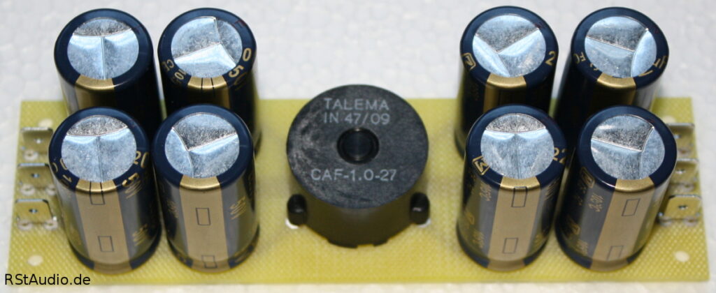
The control unit generates the unregulated DC voltage for the analog circuits (see above). In the audio units, these DC voltages are filtered once more through electrolytic capacitors and current-compensated chokes before they finally reach the actual circuits (XOno and XP-30).
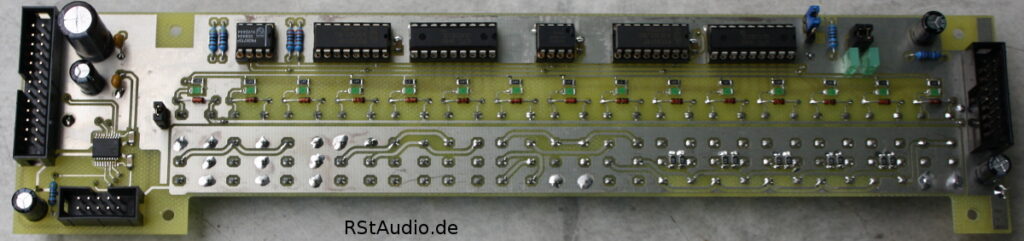
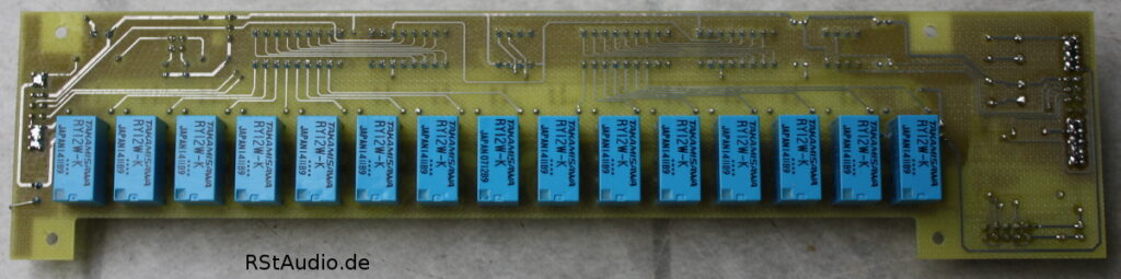
Input and Output Circuit
When designing the preamp, it was important to me to be able to replace the actual preamp board without making major changes to the overall design. To achieve this, I had to move the input and output circuitry — unlike in my VV4 — to an external board. I decided to mount this board directly on the rear panel to keep the cabling as short as possible. The necessary control circuitry is located on a second circuit board above the audio switch.
All inputs and outputs are switched via relays. This ensures that the audio circuits are electrically isolated from the controlling microcontroller. The following are switched:
- 5 line inputs – the first input is permanently hardwired to the XOno
- Tape Monitor Loop
- Differential / Single-ended inputs
- Phase Invertation at the differential inputs
- Muting for differential and single-ended outputs
- 2× differential outputs
- 2× single-ended outputs
Circuit diagrams of the input and output relay board
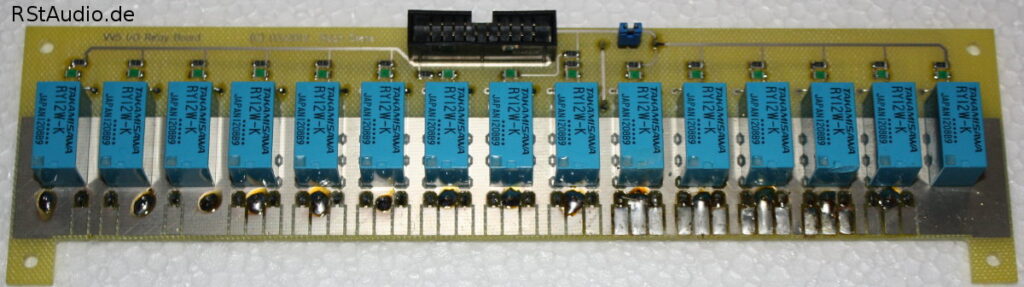
Control is provided via an I2C bus from the control unit, ensuring that no clock signal is present as long as no switching occurs. In addition to controlling the relays on the input and output board as well as the XOno relays, the board also features a connection for volume control of the XP-30. Furthermore, a temperature-sensing chip is integrated, which allows the internal temperature of the respective audio unit to be measured.
Assembly of the Enclosures
November 27, 2012
I decided to go with three Slim-Line 02/350-2U 10mm Silver enclosures (1NSL02350B) from HiFi 2000. These enclosures are really quite nice for the price, and they also look attractive. For the drilling, milling, and labeling, I used a Datron M35 again this time.
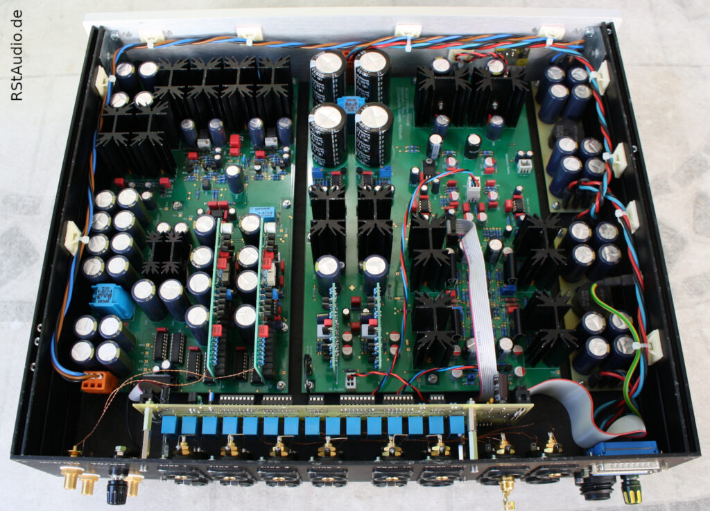
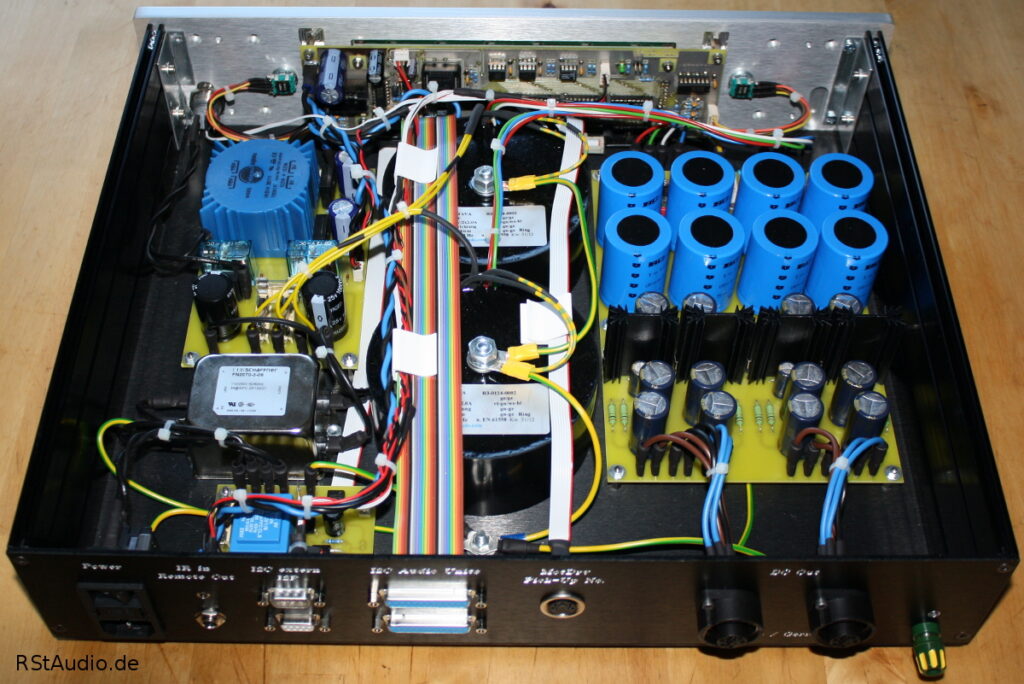
The following photo shows the layout of the electronics inside the control unit. Mounted directly on the front panel are the microcontroller board in the center, the two rotary encoders to its left and right, and the power button on the far left. The board containing the phase detection circuitry is located in the lower left corner of the housing. Above this are mounted the mains filter and the circuit board containing the DC filter and the control unit’s power supply. In the center of the enclosure are the two toroidal transformers of the audio power supply, which, as always, were custom-made for me by RONDO Ringkerntransformatoren. Almost the entire left side is taken up by the audio power supply—especially when you include the two transformers.
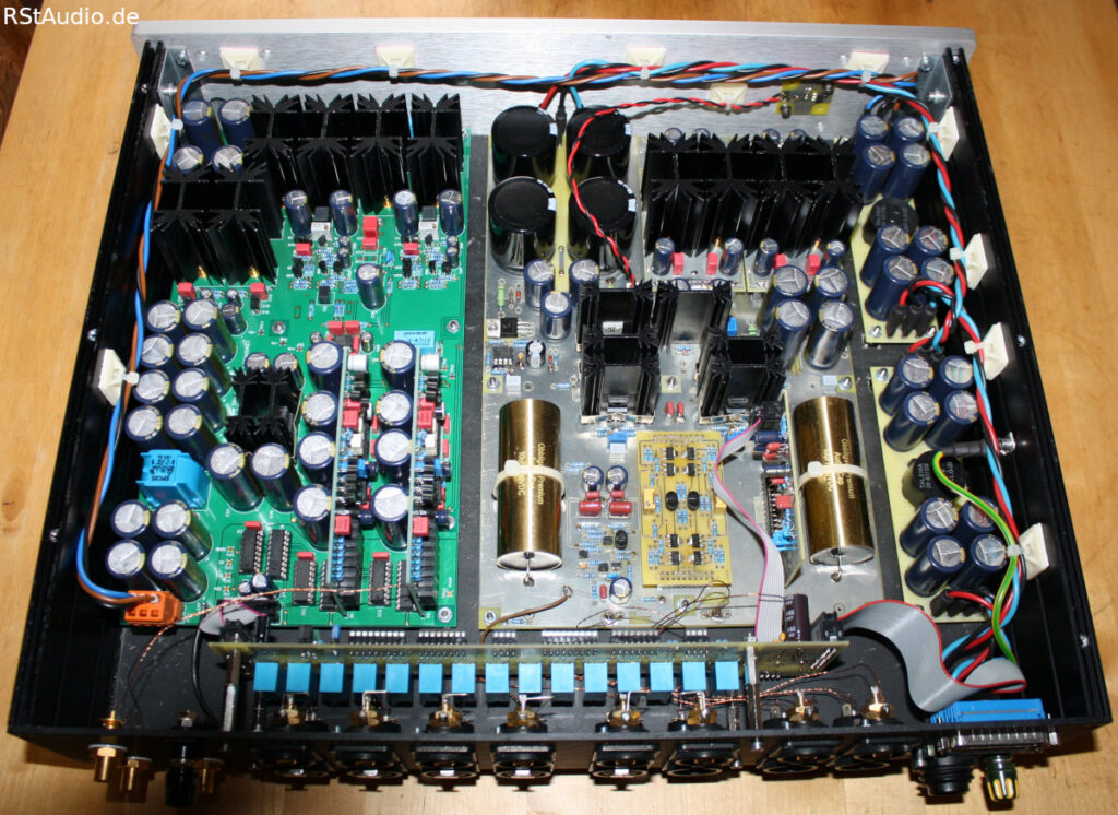
In both audio units, I covered the bottom and top panels with ADPOL heavy foil to suppress resonance. Since the spacers for the circuit boards are screwed directly onto the bottom panel, I had to cut out corresponding openings in the heavy foil. The enclosure feet are self-adhesive hemispheres made of Sorbothane.
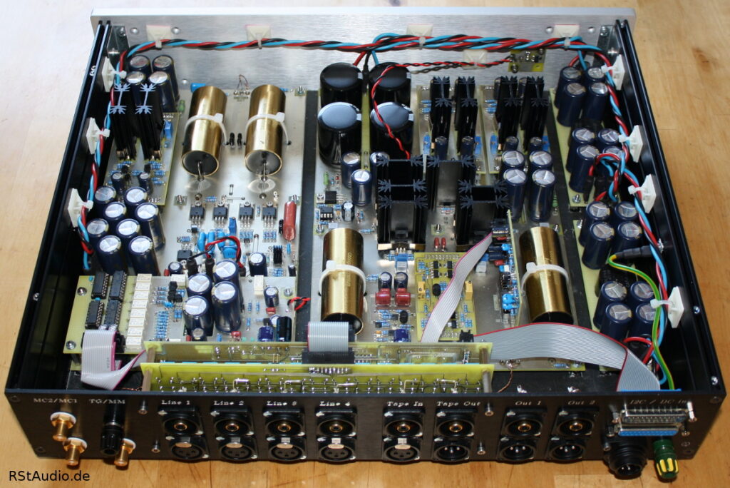
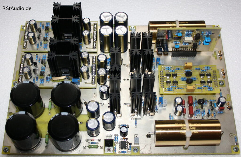
The two circuit boards are mounted on the rear panel: the relay board for switching the inputs and outputs, and above it the control board, from which the control signals are distributed. The XOno circuit board, along with its two add-on boards, is housed on the left side of the enclosure. To the right of it is the XP-30 preamp board. Finally, on the far right of the enclosure, you can see the two CLC filter boards for the XOno and XP-30.

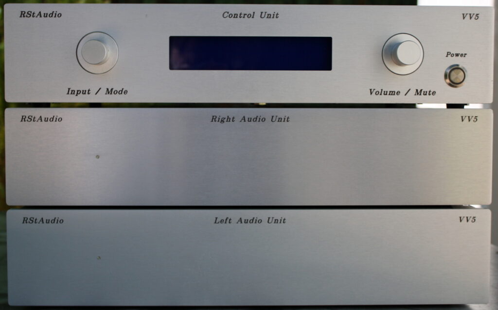
The image above shows all the preamp units stacked on top of each other from the rear. The control unit is at the top, with the right and left audio units below it. All information regarding the inputs and outputs can be found at the top.
Changes and Improvements
May 29, 2020
Of course, even good things can always be improved upon. So in the meantime, I’ve made a few changes here and there.
Power supply for the Audio Units
Snubber networks have been built into the power supply. In addition, I replaced the rectifier diodes with SiC (silicon carbide) Schottky diodes.
Input and Output Circuit
I haven’t really been happy with the implementation of the control and relay boards, as well as the inputs and outputs, ever since I set them up. When a problem arose with communication between the microcontroller and the MUSES chips, I had the opportunity to put my new ideas for these two boards into practice.
I have included the following points in my personal job description:
- Assembly on a single board; integration of the control and relay boards
- Optimizing SPI communication between the microcontroller and the MUSES chips
- Connect the audio signals directly to the relay pins (shortest signal path)
- Inputs that are not selected are connected to a defined load resistor
Discrete Voltage Regulators
I also revised the two discrete voltage regulators for the XP-30 clone and the corresponding regulator for the XOno. In doing so, I made five changes.
- Installation of a low-pass filter for the reference voltage in the controller
- frequency-dependent control gain
- Optimal operating point of the controller
- Fixed output voltage per board
- Use of larger heat sinks while maintaining the board dimensions
DPV1 Phono Preamplifier
After hearing through the XOno phono preamp for more than ten years, I decided to build my own discrete phono amplifier. I designed the DPV1 board so that it can replace the XOno board in the VV5 without any mechanical modifications.
XC-22A Preamplifier Board
For seven years, I was extremely satisfied with my replica of the XP-30 preamp board. For me, the XP-30 was — and still is — absolutely top-notch. But as the saying goes: The better is the enemy of the good. The only criticism this preamp might have to face is the AC coupling in the signal path. I have nothing against this type of circuit design in principle, but my developments over the past few years have shown me that a DC-coupled stage with a servo regulator offers advantages. Consequently, I replaced the XP-30 board with the XC-22A board in May 2020.