Table of Contents
Description of the Project
17-08-2021
Around 1995/96 I came across a description in a news group of a small very simple amplifier in connection with the 57 Quads. I very quickly got in touch by e-mail with the author Sheldon Stokes, who drew my attention to the relevant articles by Nelson Pass. At the time, the internet had not yet reached that stage and it took me two months to get copies of the two articles from the American DIY audio magazine The Audio Amateur via the local library. Today they can be easily downloaded as pdf files from the internet :
- The Pass Zen Amplifier – 10 Watts of Single-Stage Single-Ended Class A
- Return of Zen – Upgrades to the Single-Stage, Single-Ended, Class A Mosfet Amplifier
I could hardly believe that these amazingly simple amplifiers would work well with my Quads. However, I was so fascinated by the extremely simple circuit design that I had to build a pair of these power amplifiers. I have been running my Stacked Quads with these small power amplifiers for many years now (before that my electrostats ran on a modified Quad 405) and it was only in 2004 that I had the idea of replacing them with a power amplifier with more power and a better adaptation to my special load – 57 Stacked Quads.
The circuit diagram of my Zen power amplifier can be found here.
With my current knowledge, I would place more emphasis on the quality of the coupling capacitors (MKP4, Panasonic FC, Black Gate, …) when building this amplifier again. Of course, I would also incorporate the improvements to the design that have been published in the meantime (Aleph current source, buffer at the input, …). Despite everything, this little beast still exerts a great fascination on me and for this reason, too, I have decided to stick to the single-ended Class A concept when building a new power amplifier.
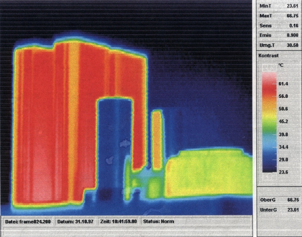
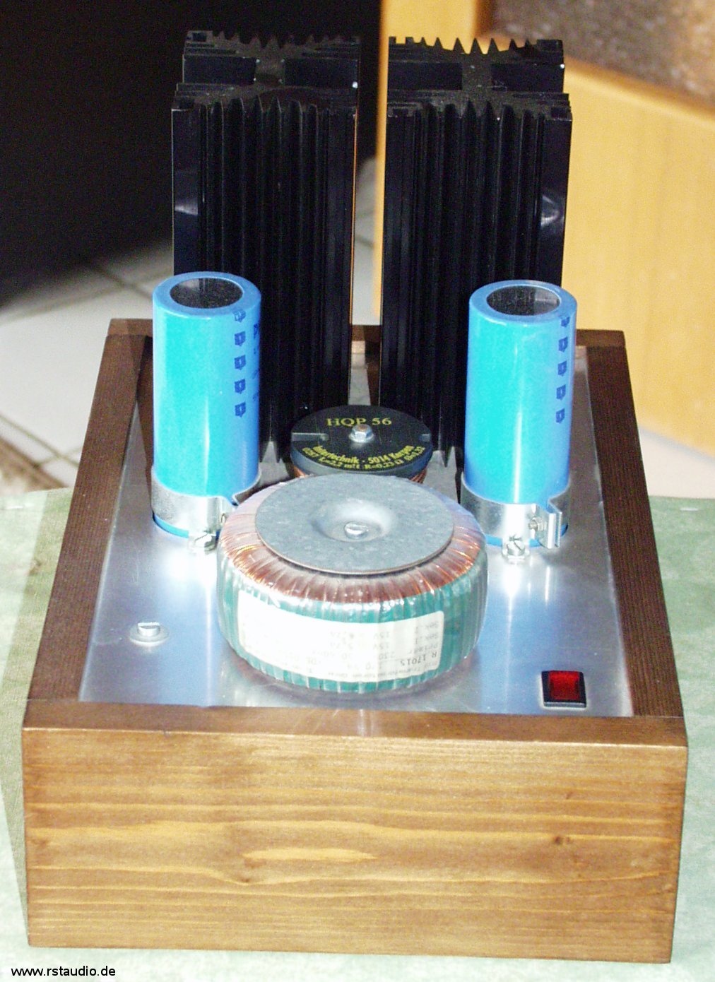
The Zen was my first real contact with a single-ended Class A power amplifier. For this reason, I misjudged the exorbitant power dissipation and used too small heat sinks for the first setup (of course, I quickly remedied this shortcoming). However, the name Energy Destroyer comes from this personal realisation. The above picture of a thermal imaging camera shows impressively what I am writing about.
A big thanks for the construction of this amplifier goes to my father, who was responsible for the very attractive construction of the cabinet in the classic design of tube power amplifiers.

Here you can see the power supply of the amplifier. It consists of the transformer, the rectifier and a C-L-C filtering.

The transformer used is a toroid with 2x15V / 5.7A, the two secondary voltages are connected in series.
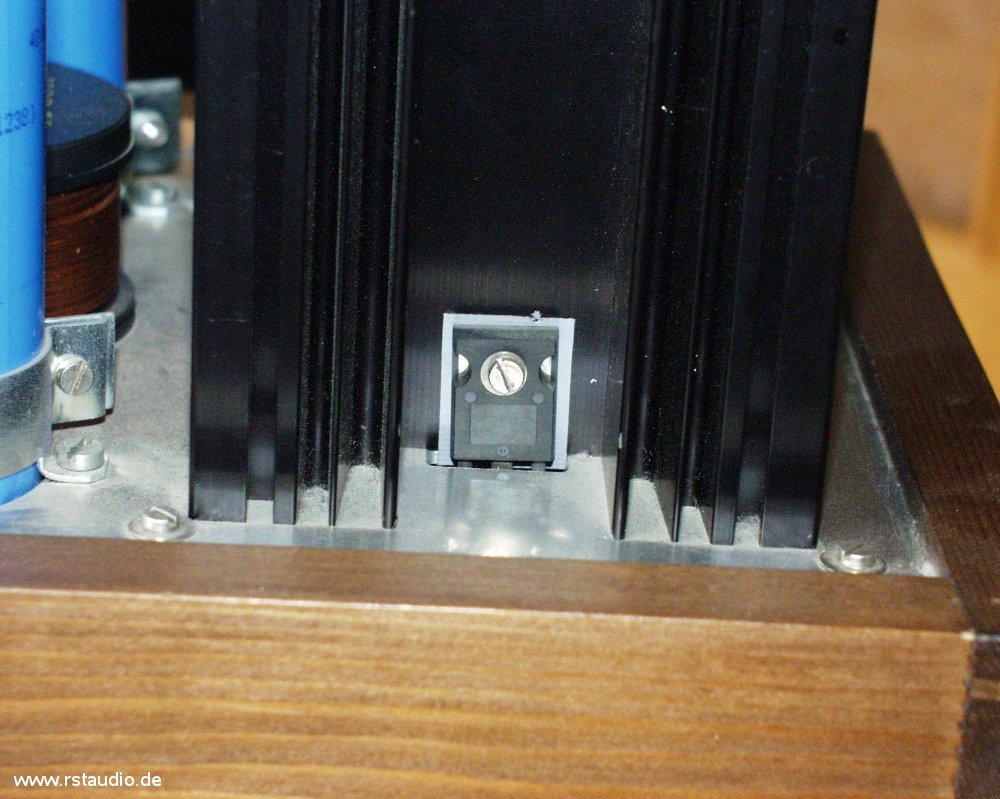
This picture shows the assembly of one of the two power MOSFETs. They are soldered directly into the board, protrude from the housing through a cut-out in the mounting plate and are screwed onto the heat sink there.
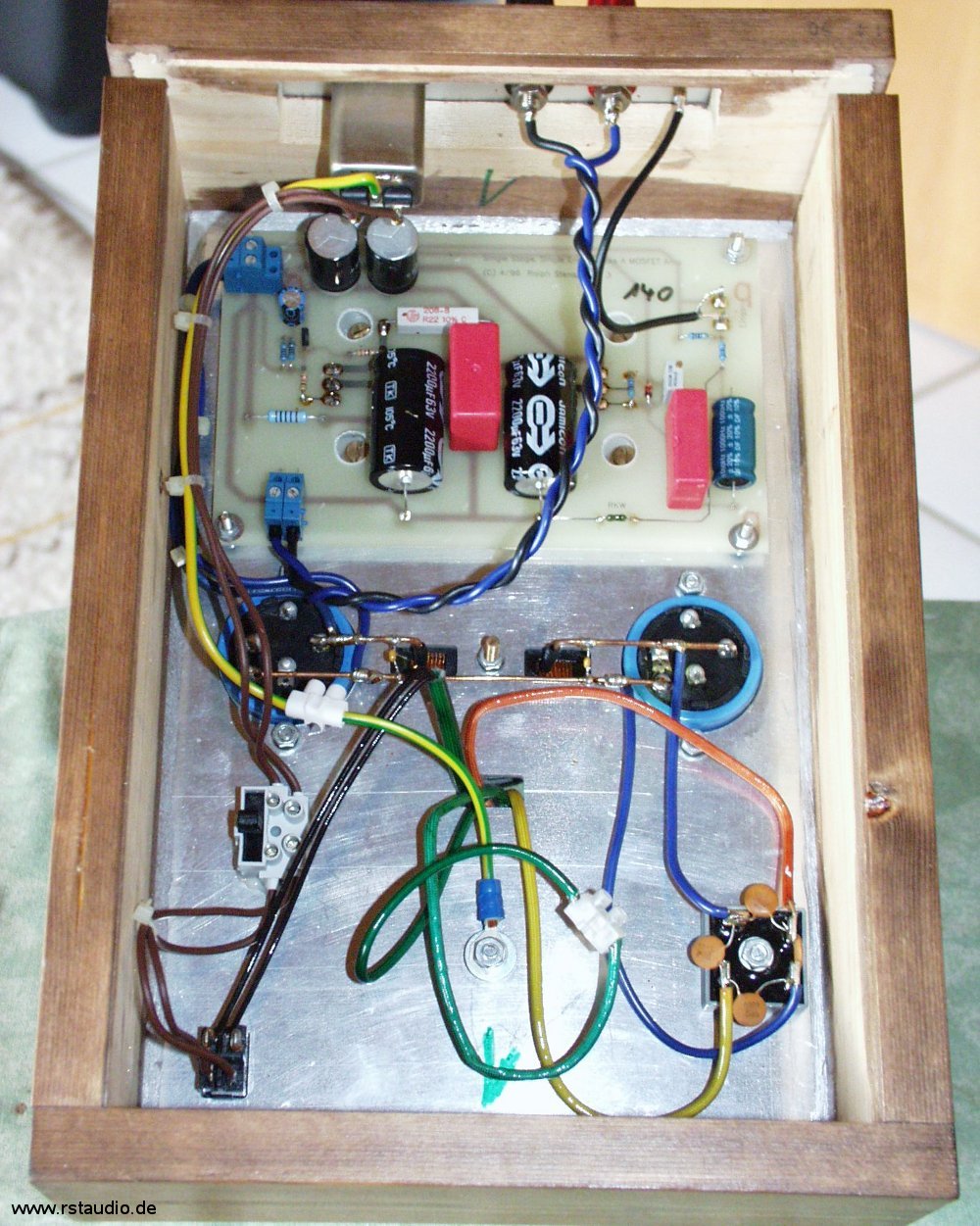
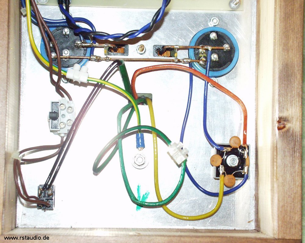
This picture gives a general overview of the internal construction. At the bottom left we see the mains switch and at the bottom right the rectifier. The earthing is clamped under the transformer’s fixing screw. Above this we find the wiring of the C-L-C filtering. On the left side, between the earth and the filtering, you can see the primary fuse. In the upper part of the picture you can see the audio board and the components of the rear panel.
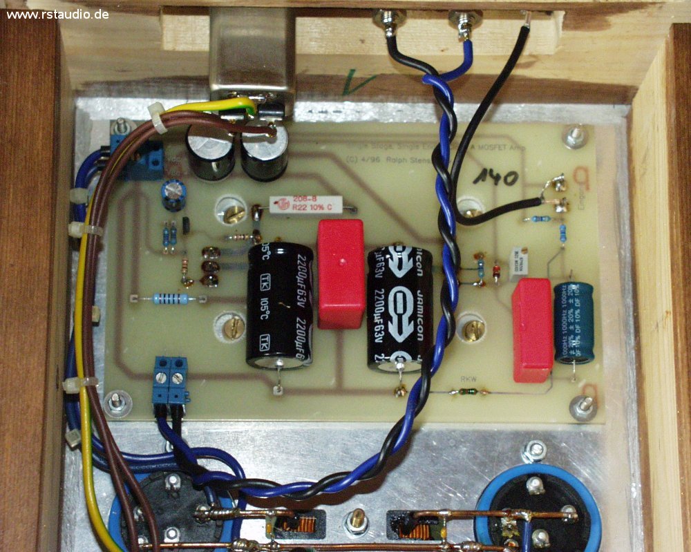
This is an enlarged section of the audio board. At the top left is the input for the DC supply, at the bottom left is the output to the loudspeaker. On the right side is the signal input.
Here you can see an enlarged section of the operating voltage supply. The ground wire is a bare, solid copper wire around which the ends of the connected wiring have been wrapped and then soldered. On the right is the capacitor behind the rectifier and the left capacitor sits at the output of the power supply. The single-pole free-floating luster terminal to the right of the earth terminal connects the two secondary voltages in series.
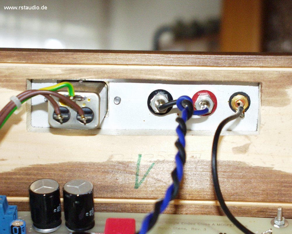
The last thing you see are the components on the back of the housing. On the left is the mains voltage input with filter. In the middle are the two terminals for the loudspeaker and on the right side is the cinch socket for the input signal.
DC Filter Modification
17-08-2021
In my Aleph P I had installed a DC filter in front of the transformer of the power supply and, contrary to expectations, was very pleased with the improvement of the sound. So it was obvious to equip the Zen power amplifier with an appropriate filter as well. Here, too, I used a bridge rectifier, but the electrolytic capacitors used have a higher value (2 × 10mF/25V). The result is amazing. The improvement is much greater than with the preamplifier and is mainly noticeable in the bass.
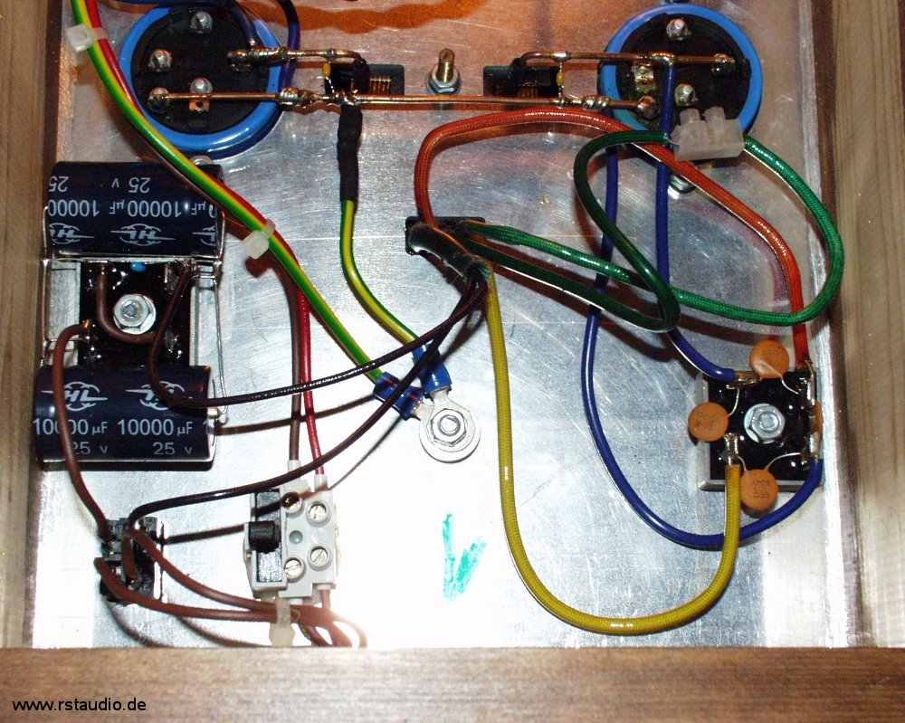
The DC filter can be seen at the left edge of the picture (centre). The electrolytic capacitors are soldered directly to the bridge rectifier.

Here you can see an enlargement of the DC filter. The small light blue capacitor is a 100nF type.
Muting Circuit
17-08-2021
My Zen amplifiers had the unpleasant property of giving a clear and relatively loud impulse to the speakers when switched on. To suppress this, I used a relay that briefly closes the loudspeaker output in idle mode.
The relay is switched by an IRF610 whose gate is connected to the operating voltage via an RC combination (which also determines the time constant for the switch-on delay). To prevent the entire 40V of the operating voltage from being applied to the gate and thus destroying the MOSFET, the gate voltage is limited to 11V by a Zener diode. The 2W resistor still visible on the circuit is in series with the relay coil and ensures a correct coil voltage with its voltage drop. All in all, it is a very simple but effective circuit that ensures that my power amplifiers now behave very “well-behaved” when they are switched on.
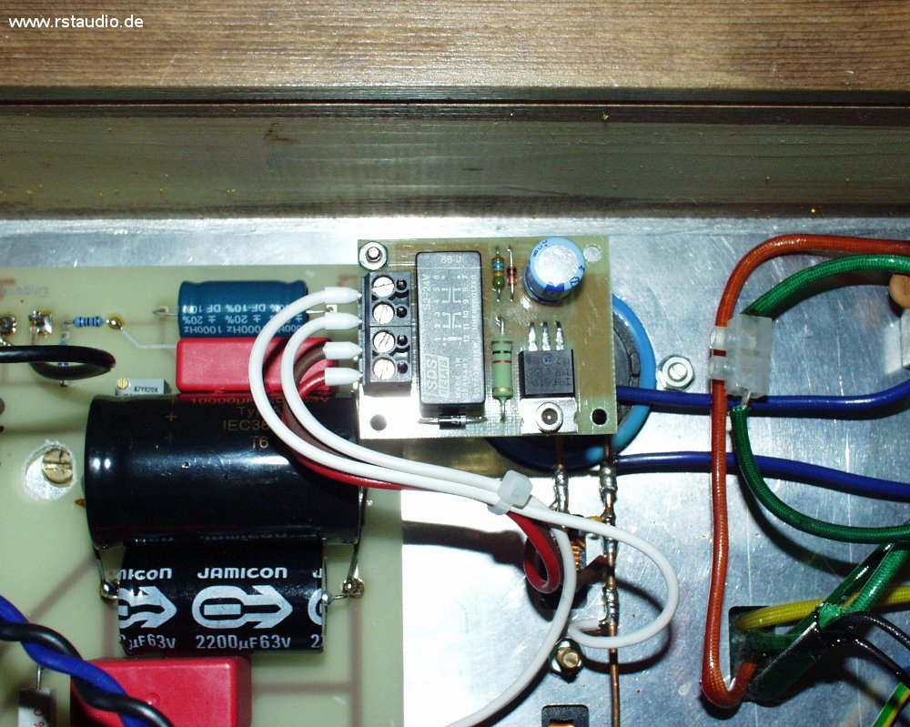
On the photo you can also see that I added a 10000μF capacitor to the original output capacitors of 2x 2200μF.