
Introduction
January 27, 2020
There’s a phenomenon related to my Quads that I’ve observed for many years but only understood in the last few weeks. The speakers have, so to speak, a “daily variation”: Sometimes they’re quieter than usual, so I have to turn up the volume to achieve the same perceived loudness. For a long time, I attributed this to my own daily form, but investigations over the past few weeks have shown that the cause lies in the speakers themselves. Fluctuations in the mains voltage (permissible: 230V/AC ±10%) directly affect the bias voltage of the diaphragms. Different bias voltages result in altered deflections—and thus a changed volume—of the Quads. To eliminate this effect, I developed the RStAudio ESL AC Voltage Regenerator.
In addition, ever since the speakers were refurbished, I’ve been having issues with distortion in the tweeter when the mains voltage exceeds 230V/AC.
Research with Spice
January 27, 2020
To confirm my suspicion, I used Spice again. This software is very effective for determining what the actual conditions on the foils should be.
My four Quads are designed for 220V/AC and initially step up this voltage to 610V/AC via a transformer. The voltage is then multiplied using a Greinacher cascade to a DC voltage of approximately 1,500V/DC for the tweeter panel and approximately 6,000V/DC for the two woofer panels. An initial simulation using these boundary conditions calculates the voltages at the speaker modules as specified by the manufacturer.
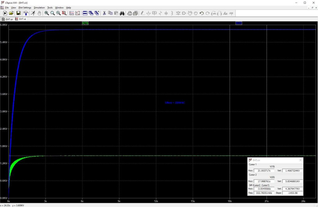
The diaphragm voltages are 1.467V/DC for the treble and 5.835V/DC for the bass. These are the ideal values specified by the manufacturer. Of course, there was also a tolerance range for the mains voltage at the time the ’57 Quads were developed, and I believe it was also around ±10% back then. However, I would argue that mains fluctuations at that time — at least in countryside areas — were not as significant as they are today.
Next, I looked at how the foils perform at an ideal mains voltage of 230V/AC.
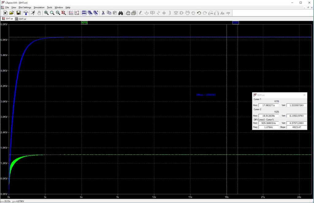
The simulation yields 1.534V/DC and 6.109V/DC. This corresponds to an increase of 67V/DC in the high frequencies and 274V/DC in the bass. That is approximately 4.6% more voltage than intended, but it still falls within the tolerance range of 220V/AC ±10%. Therefore, operating my Quads at the ideal 230V/AC is permissible.
If we consider the voltages within the ±10% tolerance band around 230V/AC, the following picture emerges:
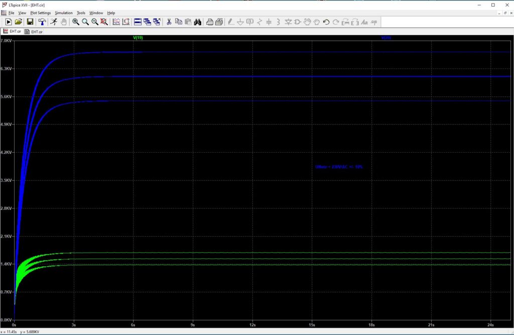
The two middle curves (blue and green) represent the results at a line voltage of 230V/AC; the two outer curves represent the voltages at 207V/AC (-10%) and 253V/AC (+10%), i.e., at the maximum limits of the permissible tolerance range for the line voltage. The resulting voltages are summarized in the following table:
| Mains Voltage | 220V/AC | 230V/AC – 10% | 230V/AC | 230V/AC + 10% |
| Tweeter | 1467V/DC | 1380V/DC | 1534V/DC | 1687V/DC |
| Bass | 5835V/DC | 5491V/DC | 6109V/DC | 6715V/DC |
As the simulations show, the actual foil voltages depend on the voltage currently present on the grid side. In the hour before I wrote these lines, I experienced voltage fluctuations of more than 10V/AC. Depending on whether the sun is shining or not, the baseline values can vary significantly, as there are numerous wind turbines and solar panels installed around our house.
However, the applied plate voltage directly affects the resulting deflection for a given input signal. As a result, the base volume of the 57-series Quads changes with the mains voltage. This is not surprising when one considers that, without regulation, the plate voltages are derived directly from the mains voltage.
Since I don’t have any models for the bass and tweeter panels, I simulated the loads on the cascade using resistors. As a result, the current flow in my simulation is directly proportional to the voltage, since Ohm’s law applies. However, I believe this limitation is acceptable and does not detract from the results.
The EHT units on my modified Quads are no longer connected to the 610V/AC secondary winding, but to a 590V/AC winding. My four Quads provide this voltage in addition to the standard output. This allows for much better matching to the intended operating points at 230V/AC than with the original wiring.
Voltage Regenerator
December 1, 2020
So what can be done to ensure stable operating conditions for the Quads?
The simplest solution is to supply the Quads with a stable input voltage that is independent of the current mains voltage conditions.
This can be achieved relatively easily using a 50Hz or 60Hz sine wave oscillator followed by a power amplifier with an output transformer.
The frequency signal is generated by a DDS chip (AD9833). A 10MHz crystal oscillator is used as the reference clock. The DDS chip must be initialized after power-up, which is why an additional microcontroller is required. I chose an EFM8 Busy Bee from Silicon Labs. This controller also handles the initialization of the digital potentiometer used to set the output voltage.
After the DDS chip, the sine wave signal is amplified, filtered, and stripped of its DC component using a servo controller. The processed signal is then sent to the power amplifier via the digitally adjustable potentiometer. I decided to use two integrated LM1875 audio amplifiers, which are connected in a bridge configuration. The transformer winding is therefore located between the outputs of the two amplifiers. The output power is rated for two 57-series Quads.
The output voltage can be adjusted slightly using a DIP switch. I have set the output frequency to a fixed 60Hz. This means that the high-voltage cascades are charged 10 times per second more frequently than with the 50Hz standard used in our region.
Of course, the circuit also requires a supply voltage. I implemented this using my usual sophisticated circuit design. The mains filter is followed by another filter containing X2 and Y2 capacitors. This is followed by a DC filter for the 230V/AC voltage. Only after these three filters is the primary winding of the 45VA toroidal transformer connected. On the secondary side, there are first snubber networks before the AC voltage is processed by a discrete rectifier with ultra-fast soft-recovery diodes. This is followed by a symmetrical CLC filter. The unregulated operating voltage is then generated by capacitive multipliers. These voltages supply the two audio amplifiers. In addition, there are ±15V and 3.3V voltage regulators to power the operational amplifiers and the digital electronics.
I used SMD components for a large part of the signal processing. These are mounted on the bottom side of the circuit board and are therefore not visible in the photo below.
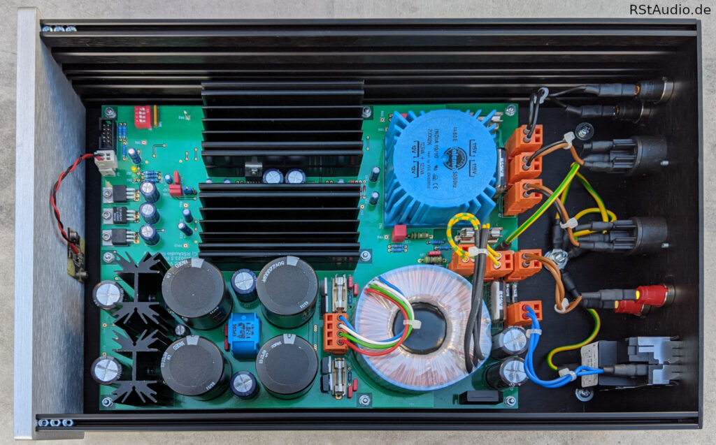
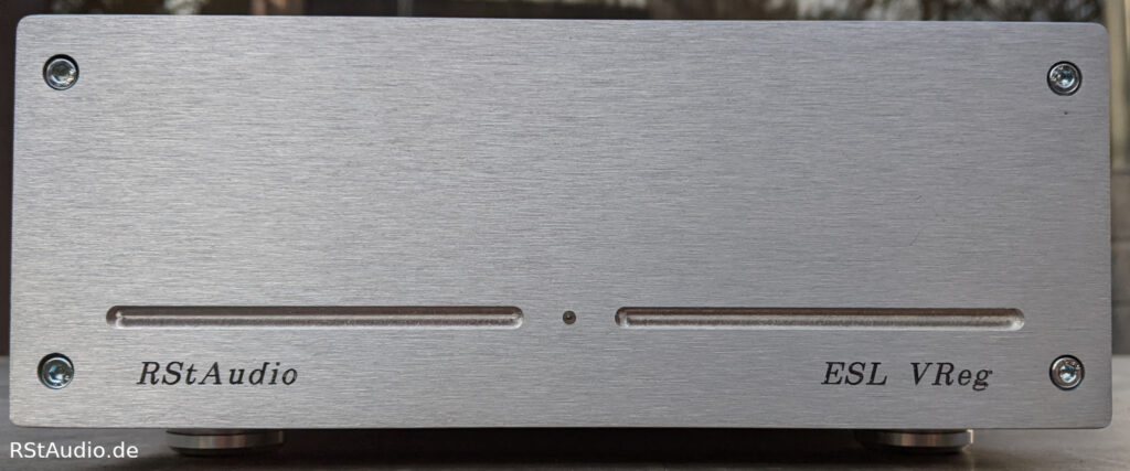
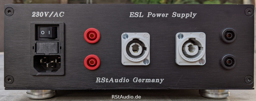
The front of the device is shown at the top of this page. It features only a single LED that indicates the operating status. The rear of the device is shown in the following photo. On the left is the 230V/AC power input with a mains filter, fuses, and a switch. The mains voltage after the DC filter can be tapped and measured at the red 4 mm safety laboratory jacks. The Quads are connected to the two adjacent Neutrik Power-Con jacks. The black 4mm safety laboratory jacks are connected to the device’s output. Here, the voltage at the Quads can be measured.
Thanks to this circuit, the Quads’ “daily performance fluctuations” are a thing of the past. In addition, there are no longer any sparks caused by excessive mains voltage. I am very satisfied with this development and the resulting performance of the Quads.
So what is the voltage situation like on my Quads? First, here are the technical specifications:
- The internal transformers in my Quads have been re-soldered to a secondary voltage of 590V/AC.
- The output voltage of the Quad ESL AC Voltage Regenerator is set to 220V/AC.
- The output voltage has a frequency of 60Hz (see above).
This results in approximately 1,450V/DC at the tweeter and 5,680V/DC at the woofer panels.