Table of Contents
- Introduction
- Description of the Circuit Design
- Installation in the Enclosures
- Audiophile Review
- VV8 CM
Introduction
07-08-2023
Since the release of the VV7 preamplifier I was asked from time to time to develop a multi-channel preamplifier without phono preamplifier. The number of desired channels was between 4 and 8. At the beginning of 2023 I decided to realize such a preamplifier with 8 channels based on the linear stage with OPA1632 from the VV7 project.
Also in this project I fell back on proven technology from the XOno 2019 project. To this day, there is no reason for me to improve anything in the corresponding circuits (DC voltage generation) and so they also perform very well in this preamplifier.
Description of the Circuit Design
07-08-2023
The core of the preamplifier is a PCB with a total of four audio channels. Two of these PCBs are installed in the VV8. The preamplifier can thus be used, for example, in stereo mode with 4 channels per stereo side. Ideal for an actively driven and up to 4 way speaker system.
Preamplifier Circuit
As I wrote above, the base of the preamplifier is an OPA1632. I have learned to appreciate this balanced operational amplifier from Texas Instruments in various projects. Rumor has it that this opamp is internally supersymmetrical, in any case it sounds stunningly good.
At the beginning of the signal path of a channel sits the digital potentiometer MUSES72320. Still the best chip you can use for this function. The MUSES has two channels and so it can be used very nicely in a balanced design. You have to load the outputs of the potentiometers with high impedance, otherwise you don’t get a linear attenuation (keyword: loaded voltage divider). I decided to use a discrete buffer amplifier with 2SK2145 JFETs.
The circuit with the OPA1632 is then connected to the buffer. It can be designed with low impedance and thus the excellent inherent noise of the OP is not degraded. Integrated high-current buffers are connected to the two outputs of the balanced operational amplifier. They are included in the feedback loop of the OPA1632. With these drivers, even larger line capacitances do not cause any problems. The integration into the feedback additionally guarantees the neutrality of these drivers.
The last circuit part of a linear stage is a servo controller. This ensures that the outputs are free of DC voltage components, so that the linear stage can be operated without an output coupling capacitor.
On each PCB there is still a balanced voltage regulator with the modified topology according to Walt Jung that I favor. However, I had to adapt the modified Jung regulator to the lower operating voltage. Furthermore there is a potential separated digital control to the controller on the board.
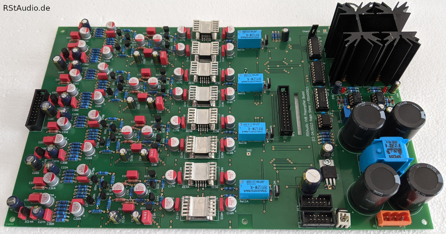
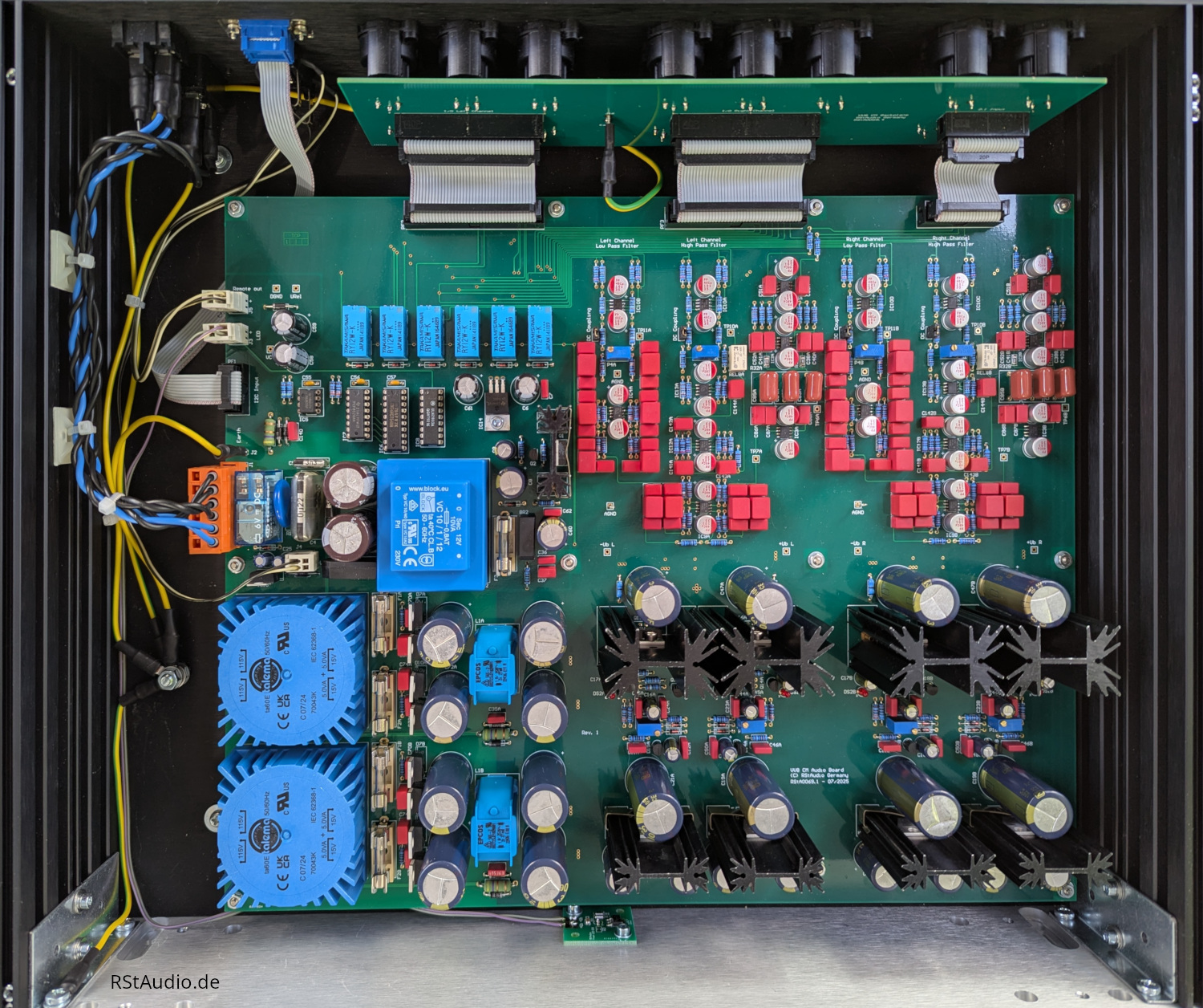
In the photo above, you can see the audio circuit board looking at the top. On the left side the preamplifier stages are placed. To the right, in a narrow strip on the PCB, is the digital control. On the far right you can see the power supply.
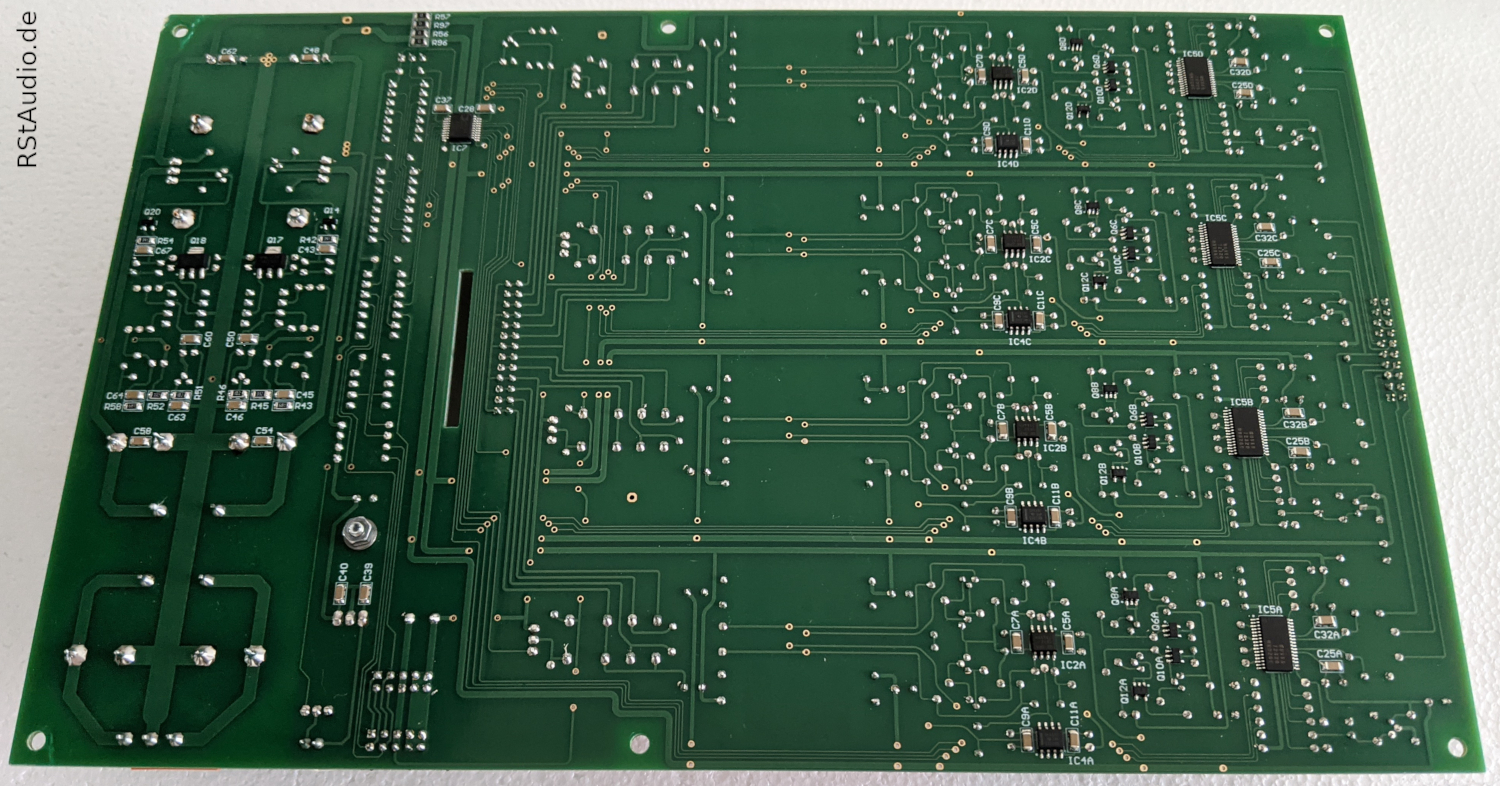
As you can see from the photo above, many of the components on the VV8 are SMDs. I placed most of them on the bottom of the board. Usually this leads to a simplified layout.
For each audio circuit board there is a backplane with the required XLR connectors. This PCB is connected to the linear stages with 2 ribbon cables.
Power Supply
The construction of the power supply can be found in some of my designs by now (XOno 2019, VV5.4, VV7). Also in the VV8 you can find the proven chain of Schurter mains socket, 230V/AC DC filter, toroidal transformers from Müller Elektrotechnik and the PCBs for the unregulated operating voltage supply.
The design for generating the unregulated balanced DC voltages for the analog circuits are still state of the art for me and no changes are necessary from my point of view.

Control
In the center of the controller sits again the AT89C51ED2 microcontroller from Micro Chip, a device I prefer at this point. You can find it also in all other preamplifier projects of mine.
A SPI and a I2C bus are used. Both serial data transmissions are in a static state as long as nothing is switched. Interference in the analog circuits is thus excluded during normal operation, but also during a switching operation, the potential separation between the digital and analog circuits guarantees interference-free operation.
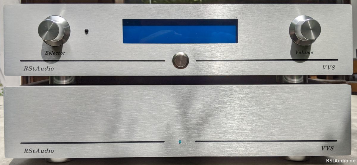
The preamplifier is operated by means of two rotary encoders with pushbuttons and an LC display with 2 lines and 20 columns. In addition, there is a remote control that emulates the function of the rotary encoders. Another control element is a pushbutton on the front panel, which is used to switch the preamplifier on and off.
Installation in the Enclosures
07-08-2023
The amount of material is so great that two enclosures per preamplifier are necessary, not really something special with my designs. For the division of the electronics I took my cue from the VV5.4 preamplifier. Of course I took again the proven enclosures from Italy.
Control Unit
The control unit contains the 230V/AC supply, the generation of the unregulated DC voltages and the microcontroller system.
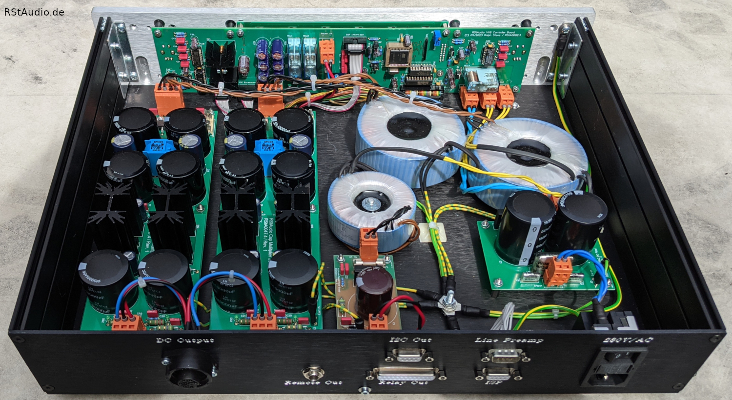
On the photo above you can see the setup. Behind the front panel the printed circuit board with the microcontroller system is screwed. On the right front of the photo you can see the PCB with the 230V/AC DC filter. Behind it are the two toroidal transformers for the power supply of the audio circuits. The third smaller transformer is for the digital circuitry.
The small circuit board with the unregulated power supply for the digital circuits is located in the center front. To the left of this are the two unregulated power supplies for the analog voltage supplies.
Audio Unit
The Audio Unit houses the two audio circuit boards including the associated backplanes.
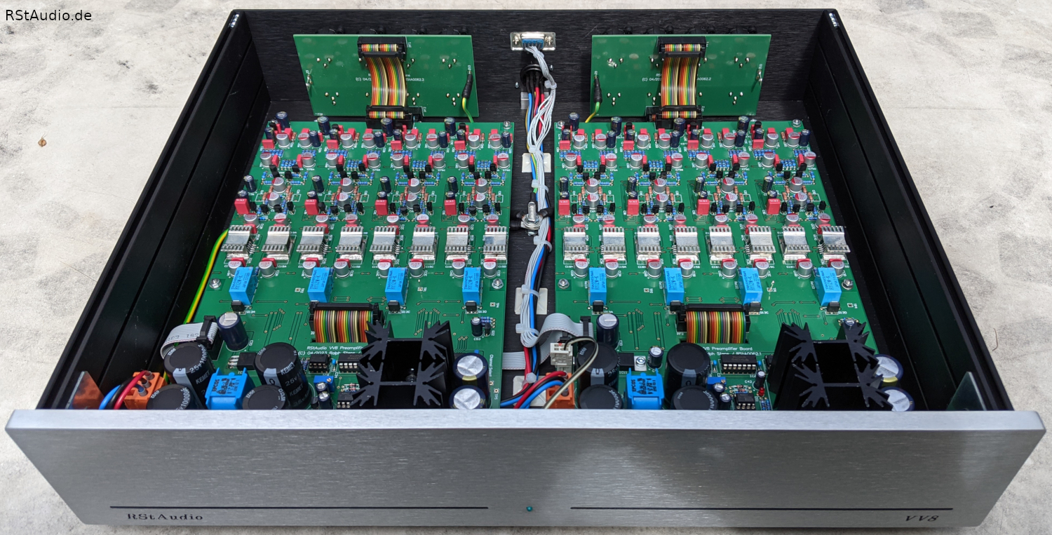
You can see in the photo above that the Audio Unit enclosure is also very well filled with the two audio PCBs and the associated backplanes.
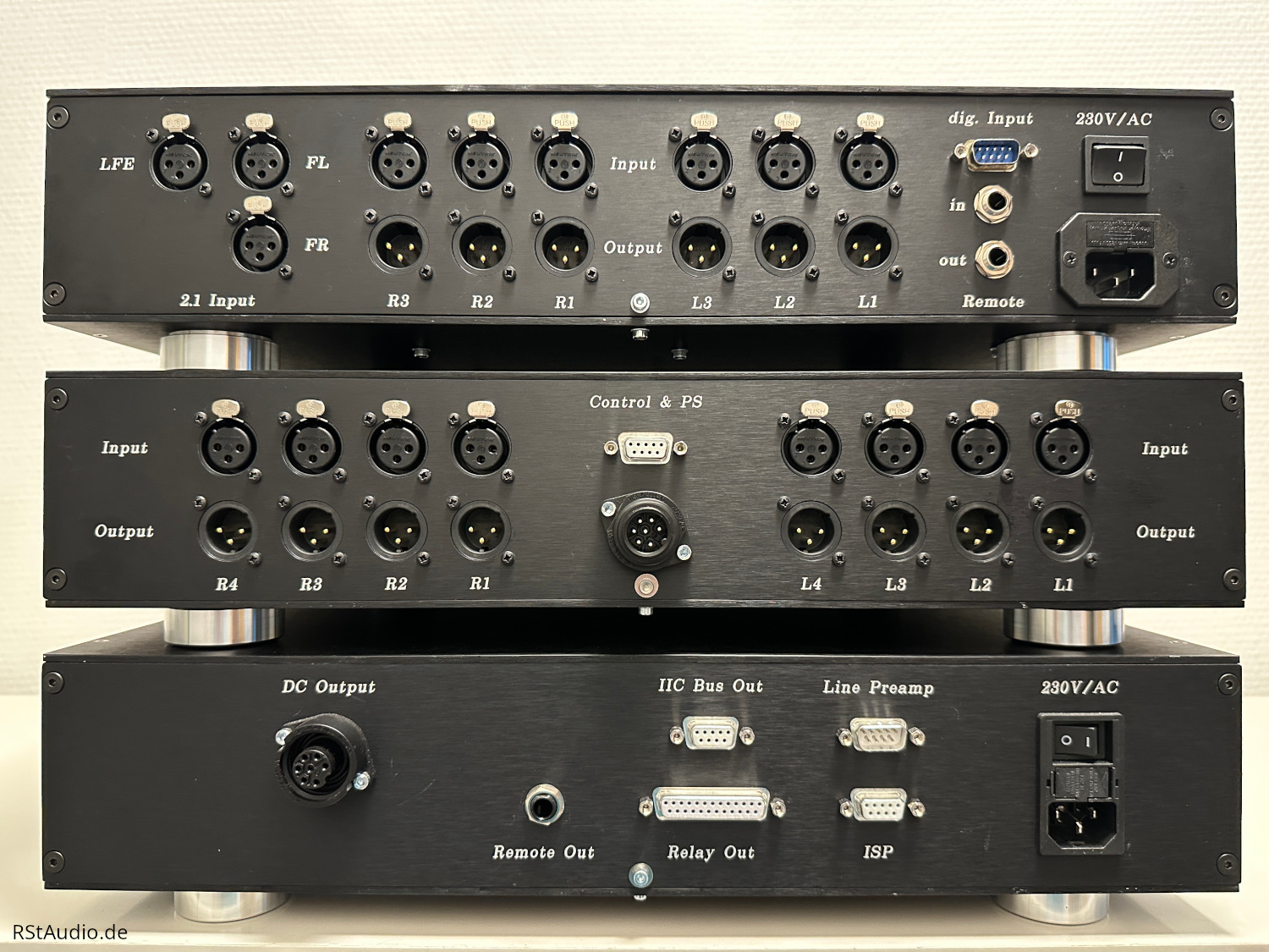
Connections
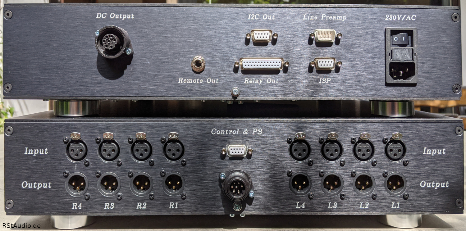
If you look at the back of the VV8, you will naturally see the preamplifier’s connections. In the photo above, the Control Unit is on top of the Audio Unit. Of course, this can be easily recognized by the type of connections.
On the right side of the Control Unit is the mains socket with switch, fuses and mains filter from Schurter. To the left of this, labeled Line Preamp, is the connection cable for the control between the Control and Audio Units. It is a normal 9-pin Sub-D cable. The socket labeled ISP can be used to supply the microcontroller with new embedded software.
The Sub-D connectors in the center of the rear panel are intended for expansions. The I2C Out socket carries an isolated I2C bus. There is no application for this yet. The socket labeled Relay Out can be used to connect an audio switcher with 5 balanced inputs.
The Remote Out jack carries a control voltage that can be used to turn other components in the system on and off.
The leftmost socket on the rear panel of the Control Unit is another connection to the Audio Unit. Here the audio circuits are supplied with voltage. A 7-pin cable is used, which I assemble myself.
In the center of the Audio Unit you can see the counterparts to the two connections with the Control Unit. These connectors are labeled Control & PS. Above is the Sub-D cable for the control unit, below is the cable for the power supply of the audio circuits.
To the left and right of it you can see the XLR connectors for the audio signals. At the top are the inputs and at the bottom the corresponding outputs. There are two groups, which are of course assigned to the two audio circuit boards. Accordingly, the individual inputs and outputs are labeled L1…L4 and R1…R4. If you look at the audio unit from the front, the audio connectors are also “correctly” arranged.
Audiophile Review
14-11-2023
Ralph Stens
Since I already know the circuitry very well from my VV7 preamp, there were actually no surprises. The VV8 plays at the high level I expected from it. A very successful design created for a high-end system with a topology similar to my RQM speaker system, i.e. an active multi-way system with digital crossovers.
Karl S.
I have been in ownership of the VV8 for a few weeks now. My previous preamp behind a Lynx Aurora was 6 channel and asymmetrical. However, I had the wish to still try 4 way / 8 channels.
So 8 channels, balanced, each channel for itself and over all controllable and a balance control was on my wish list. I had heard the VV6 at Heiner F. and so I contacted Ralph. It happened that he was already planning the VV8. To be honest, I had no great expectations of the sound of the preamp, it already sounded very good.
Now, after a few weeks, I can say that my system has completely improved with the VV8. No matter what I pay attention to, spatiality, timbre, airiness, staggering and size imaging, everything is a bit more beautiful and real. The VV8 has far exceeded my expectations. A great 8 channel preamp.
My Music System:
- Lenco with Mørch DP8 and Ortofon Windfeld
- RStAudio XOno and D3a Phono
- Lynx Aurora, Acourate, VV8
- Power Amplifiers all DIY:
Bass Pass F5, Mid Vt52, Mid-high 300B, High AD1 - Loudspeaker:
Large Bass Horn, Sato Horn with Drivers from D. Hampel, JBL2344 with TAD2001, Fostex T825
Uli J.
The choice of my audio devices has always been made with care and therefore for a longer operating time.
Now I’ve been using Ralph’s ideas and the resulting VV8 preamplifier here for weeks and would like to write a few lines about it.
If you dare to unscrew the covers, you will not see amateurishly assembled circuit boards, but extremely clean and structured electronics in all respects.
This preamplifier is designed for up to 8 channels. Ideal for an active solution with up to 2x 4 converters. In order to be able to compare it with other preamps, I tested this preamp with two power amplifiers and passive loudspeakers.
There are sound definitions ranging from digital coldness to tube butter lard.
If you appreciate one extreme or the other, then the VV8 is unsuitable, because the VV8 simply doesn’t sound. In my opinion, this is the greatest compliment to an audio device. It is simply wonderful when there is no signature and the music stands alone.
The features described in 2-channel mode are not diminished in 6 or 8-channel mode. Simply wonderful!
VV8 CM
13-09-2025
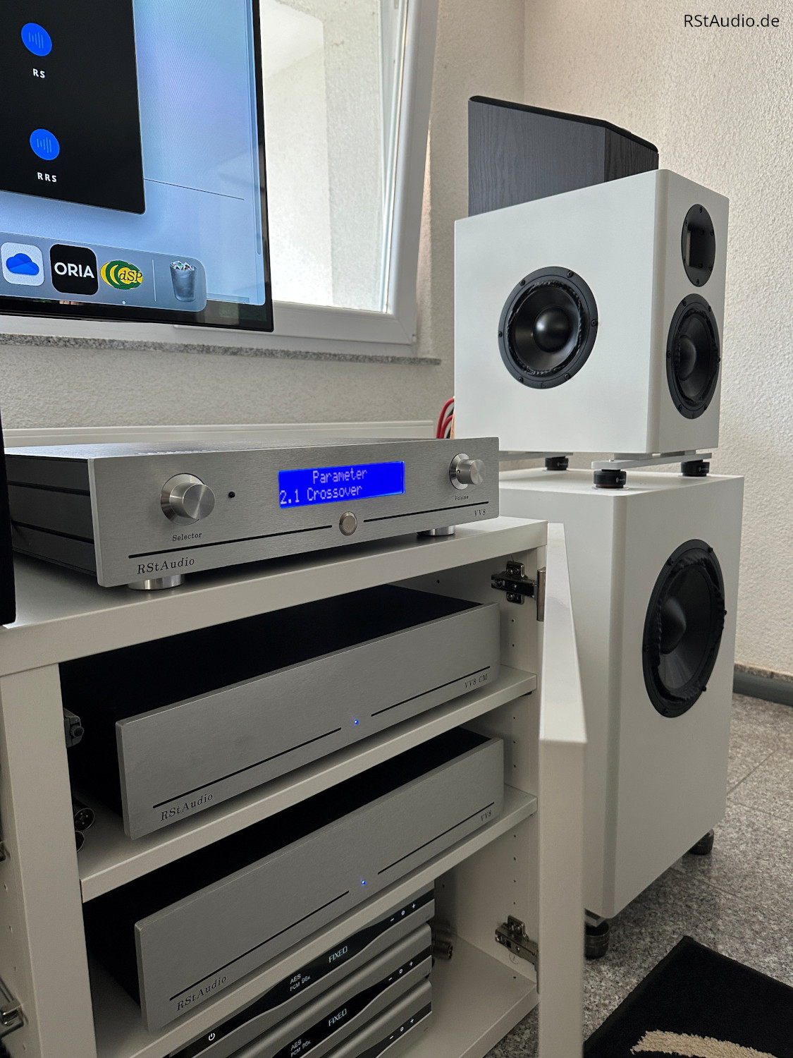
In early 2025, Carousel asked me to develop an extension for his VV8. The hardware was to include a multiplexer and an active 2-way crossover, allowing him to switch between his 9.2.6 system and stereo playback.
I decided to put everything on one board. However, I didn’t want to forego tried-and-tested technology. Dual-mono power supplies with capacity multipliers and Jung regulators are used for the active filters. The filters themselves are 4th order Linkwitz-Riley filters, which have been implemented using a Sallen-Key topology. The frequency-determining components (R & C) in the crossovers are all measured to an accuracy of ±
I gave the system the additional designation CM for Crossover Multiplexer.
When the device was delivered, I asked Carousel for a description of his system:
I have two sound systems in my listening room. There is a stereo system with three-way active crossover speakers. And there is a 9.1.6 surround sound system, for which the .1. LFE signal is sent to two 10-inch subs. So it could be called a 9.2.6 system.
There are two preamplifiers for these two systems. There is an eight-channel RStAudio VV8 preamplifier, with which I only use six-channels for my two three-way active crossover speakers for stereo. And there is an SPL MC16 for sixteen channels of surround sound.
The challenge here was that, when playing surround sound, the front left and right channels were sent only to the 6.5-inch midrange drivers. These are very capable drivers with very flat response from 100 Hz to 5000 Hz. But I was missing out on high-end for surround sound.
Therefore, I asked RStAudio to build a crossover multiplexer. When playing stereo, the VV8 CM would pass through six channels (stereo three-way) with no loss in quality to the main VV8 preamplifier. And when playing surround sound, the VV8 CM would take three-channel 2.1 input from the SPL MC16 preamplifier… that is, front left, front right and LFE subwoofer feeds… and split the LFE subwoofer channel for the two 10-inch subs… while also splitting the front left and right channels at 2500 Hz to feed the mids and the tweeters separately.
As an added complication here, when in 2.1 mode, the VV8 should pass through the signal from the MC16 at 0 dB. But, to avoid blowing the tweeters at any point by feeding them a line-level signal by accident, whenever the VV8 would be switched between modes, it should be placed in mute automatically. And if not in pass through mode, then it should default to a given selectable setting, -50 dB in my case… as well as to be in mute.
RStAudio did a wonderful job of this. As an additional “surprise and delight”, which was not in the original specification, the option to use a time-delay was built into the high-pass filter to adjust for the fact that my tweeters and midranges are mounted in the same vertical plane. This can be turned off or turned on.
Many thanks to RStAudio!
Carousel, September 2025
You can also find some information about the system on the Audio Science Review Forum.