Table of Contents
Introduction
August 10, 2016
The idea of building my own DAC has been on my mind for many years. In the meantime, I’ve come up with at least four designs, all based on Burr-Brown/Texas Instruments converters. Unfortunately, I haven’t built any of them. In mid-2015, I made another attempt.
Unlike in my previous circuits, this time I wanted to use the ES9018 — the SABRE32 Reference Audio DAC — from ESS Technology. However, I discovered that there are no publicly available datasheets and that you have to sign a confidentiality agreement to access these documents.
In the end, the whole process was too time-consuming for me, so I started looking for pre-made circuit boards for this chip. I found what I was looking for at Twisted Pear Audio, whose Buffalo-IIISE DAC I used in my DAC as a dual-mono version — that is, two boards in total.
The complete DAC consists of two modules containing the following circuit components:
- DAC Signal Module
- Amanero Technologies USB OEM Combo384 Modul
- Twisted Pear Audio Hermes-Amanero USB Isolator Modul
- Twisted Pear Audio Cronus Re-Clocking Modul with 45.1584MHz / 49.152MHz Rhea Paar
- 2× Twisted Pear Audio Buffalo-IIISE DAC
- 2× RStAudio I/V Converter
- 2× RStAudio discrete symmetrical voltage regulators for the I/V stage
- 2× RStAudio discrete voltage regulators for the DAC modules
- 2× RStAudio integrated voltage regulators for the digital front ends
- DAC Power Supply Module
- 230V/AC Supply
- 2× unregulated symmetrical power supply for the analog circuitry
- 2× unregulated power supplies for the DACs
- 2× unregulated power supplies for digital front-ends
- Remote On/Off
Hardware Description
October 13, 2016
Below, I describe the hardware in detail. I don’t have schematics for some of the purchased circuit components, and for others, I’ve decided not to publish them. Nevertheless, I hope that some of this information will be of interest, especially to DIY enthusiasts working with Twisted Pear Audio DACs.
Amanero USB Interface
While searching for a USB interface for the DAC, I quickly came across the boards from Amanero Technologies. These boards can now also be ordered directly from Twisted Pear Audio. It was particularly important to me that the interface operate asynchronously and support all current high-resolution formats. With 384kHz I2S and DSD512, this board is currently very well equipped. I purchased the board directly from the manufacturer and had to install different firmware to use it with the Cronus module (see below). Using this module with my Windows 7 PC as the source and the Twisted Pear Audio modules as the receiver works perfectly without any issues.
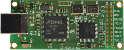
The board operates in slave mode when used in conjunction with the Cronus/Hermes boards. As mentioned above, this requires installing different firmware. The board has two chips that need to be programmed. The CPLD receives the “Slave_For_1080” firmware, and the CPU receives the “firmware_1096c3w2” firmware. You can download everything, including the drivers for Windows, from the manufacturer’s website. There you will also find instructions describing how to perform the programming. If you follow these instructions exactly, the firmware will work properly.
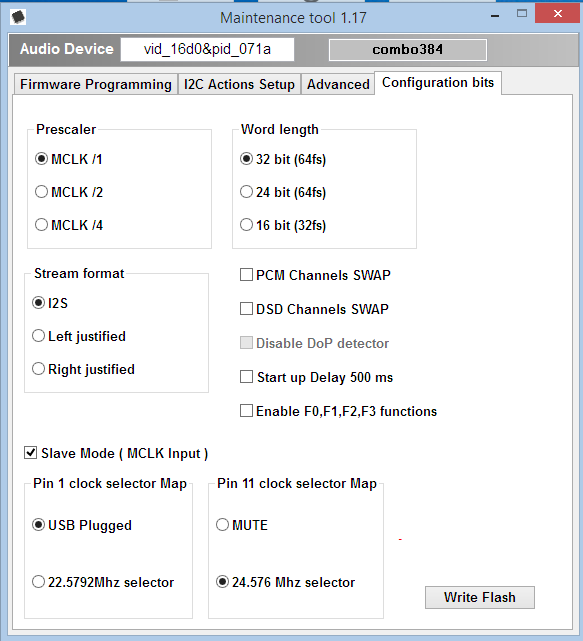
You can also read all about it in this thread on diyaudio.com. The screenshot above is also available there. After updating the firmware, the board’s configuration bits should be set according to the instructions above.
If you order the board directly from Twisted Pear Audio, it is already configured for use with Cronus and Hermes. Therefore, there is no need to reprogram the firmware.
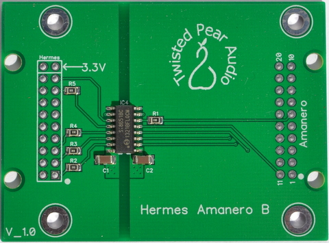
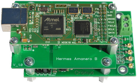
Hermes-Amanero
This module allows the Amanero Technologies USB module to be used in conjunction with the Twisted Pear Audio Cronus module. In this configuration, the USB module is fully isolated and operates in slave mode, meaning it does not generate its own clock signal but instead receives it from the Cronus module. To quote developer Russ White:
This is not really simply reclocking – it is in fact simply a perfectly time aligned USB source.
I have nothing to add to that statement.
Cronus and Rhea
The Cronus module is an electronic circuit that generates clock signals with very low jitter. It is used to replace the master clock of a source device, in this case the USB port. To achieve this, two extremely low-noise crystal oscillators — known as Rhea modules — are used. I opted for the modules with the higher frequencies (45.1584MHz and 49.152MHz). They form the basis for the 44.1kHz and 48kHz clock families in digital signal processing.
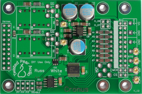
When using the Rhea clocks described above, it is important to set the clock divider to 1:2 on the Amanero side. To do this, you must move a jumper on the Cronus board.
The Hermes board is designed so that all three boards can be stacked on top of each other using connector strips. This results in the shortest possible connections, a very high level of operational reliability, and a small footprint (see image below).
Buffalo-IIISE DAC
As I mentioned above, both boards are based on the ESS Technology ES9018 SABRE32 Reference Audio DAC. This is a chip with a total of eight D/A converters, four of which are connected in parallel on the Buffalo-IIISE board. This results in a stereo DAC with improved noise performance. In the dual-mono version I used, you take two boards and connect the two channels on one board, so that eight D/A converters are connected in parallel, achieving a further improvement in the signal-to-noise ratio.
Care should be taken when wiring the I/V stage. In mono configuration, the two analog outputs on the Buffalo-IIISE are not assigned the same signals. However, everything is explained clearly in the manual.
leonvb-buffalo_iii_dac_integration_guide_v2.1.3.pdf
You can download it from the manufacturer’s website.
I/V Converter
The DACs provide balanced output currents. An I/V stage must be designed to optimally convert these signals into voltages and be adapted to the specific characteristics of balanced signals. The implementation described here uses integrated circuits. The balanced OPA1632 from Texas Instruments is particularly well-suited for this purpose, as this chip offers exceptional audiophile-grade performance.
The entire circuit for a single channel consists of two OPA1632s connected in series. The first is configured as a current-to-voltage converter. This stage is followed by a passive, balanced low-pass filter. Since all digital signals in the DACs pass through an oversampling stage and the output signal is correspondingly high-frequency, the filter can be designed very simply — in this case, it is a first-order filter. The second OPA1632 serves as a voltage amplifier and output driver.
The instructions listed above specify a sizing guideline for the I/V stage. For eight DACs connected in parallel, as is the case with the mono configuration, a resistance value of 360Ω is recommended for the current-to-voltage converter. However, with this design, the level after the first OPA1632 is significantly too high and must be reduced again by the second stage. I didn’t like that, so I reduced the two resistors in the first stage to 150Ω and adjusted the gain of the second stage to match the output level of my SACD player.
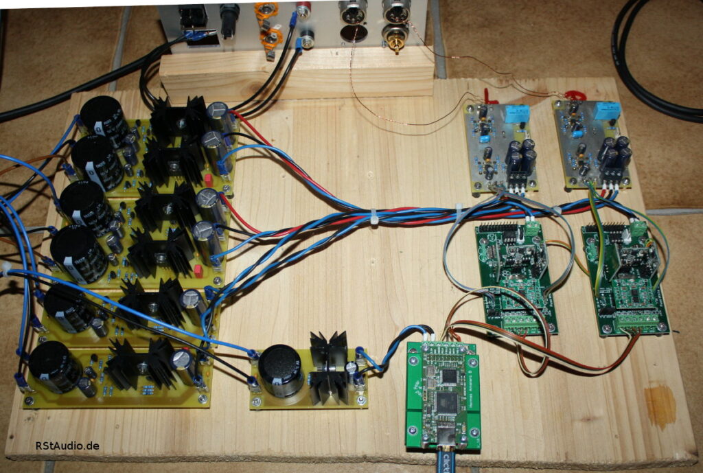
Power Supply
As is usually the case in my designs, the entire power supply from the DACs onward is configured as a dual-mono system. Naturally, this isn’t possible with the digital front end.
For the voltage regulators in the I/V stages and the DAC boards, I rely on the proven discrete voltage regulators that I also use in my VV5: the Pass regulators that I have modified. The regulation circuits for the I/V stages are symmetrical, while the regulation circuits on the DAC boards each handle only a single voltage. I power the purely digital circuits with voltage regulators based on the LT3080 from Linear Technology. This is a truly remarkable and versatile chip.
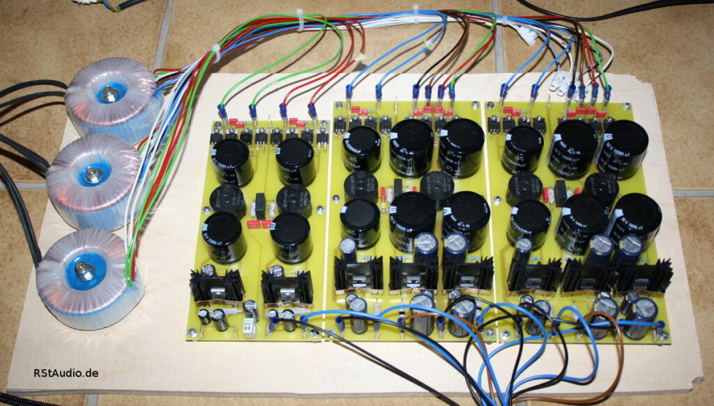
The unregulated DC power supplies in the power supply module are located before the regulators. A 230V/AC DC filter is positioned in front of the transformers. Snubber networks are connected between the secondary windings of the transformers and the rectifiers. The rectifiers are built using discrete ultra-fast soft-recovery diodes, followed by a CLC filter with relatively large electrolytic capacitors. Finally, at the output of all unregulated power supplies, there are capacitance multipliers — as mentioned, proven technology, just like what you’ll find in my preamp.
The entire power supply chain for the I/V stages is designed to provide a voltage of up to ±32 V DC for the analog circuits. To keep the power dissipation of the regulators within a reasonable range, the transformers are equipped with taps for the secondary voltages.
Reconstruction 2023
December 27, 2023
Unfortunately, the board has remained in this configuration since 2016. Furthermore, since I started using the Lynx converter, I no longer need the DAC in my system. However, I always felt it was a shame to leave the Buffallo-IIISE — which sounds excellent — lying around unfinished.
For some time now, I’ve been using a Curryman DAC with a Raspberry Pi 4 on my DHA headphone amplifier. This setup is also just mounted on a piece of board. It seemed like the right time to finally tidy things up and put the Twisted Pear DAC into a proper enclosure. It’s meant to replace the Curryman DAC on the DHA. Sonically, this is certainly a step in the right direction.
However, a lot has changed in my design approach since I built the ES9018 DAC board. I no longer use the discrete Pass voltage regulators I used back then; instead, I now use modified Jung regulators. So I’ve developed a new design based on the circuit boards from Twisted Pear and Amanero.
My goal was to build the system using just a single enclosure. Given the amount of effort I put into the power supplies, that was quite a challenge. I also decided to fit all the electronics onto a single circuit board. On top of that, I still needed to leave room in the enclosure for the three toroidal transformers.
To power the balanced I/V stages, I now use a power supply per channel that includes a capacitance multiplier followed by a modified Jung regulator. The power supply for the Buffalo-IIISE boards consists of a capacitance multiplier followed by a TPS7A4700 voltage regulator. An integrated regulator with exceptional technical specifications. The digital front end is also powered by a power supply that first uses a capacitance multiplier, followed by an LT3080 regulator. I had already used a similar setup in the board layout shown above.
Naturally, all power supplies use discrete bridge rectifiers with ultra-fast soft-recovery diodes. As is my custom, snubber networks are also included. All rectifiers are followed by CLC filtering with a current-compensated dual choke.
In addition, there are a few other circuit components that all had to be placed on the board:
- Remote in
- Remote out
- 230V/AC DC-Filter
The core component of the I/V stages remains the excellent, balanced OPA1632. I use two of these per channel. The first stage is a classic transimpedance amplifier that converts the balanced output currents from the DACs into a corresponding voltage. This is followed by a second-order active Bessel filter with a cutoff frequency of 75kHz. Due to the inverting topology of the OPA1632, the filter was implemented using a multiple-feedback structure. The output is kept offset-free with the help of a servo controller. I selected all gain- and frequency-determining passive components in the stages using a high-quality LCR meter.
I added a potential-isolation module between each of the two converters and the digital interface. The two 2×3 digital input lines for the two DACs are exactly the same length. This helps me avoid any differences in signal propagation time.
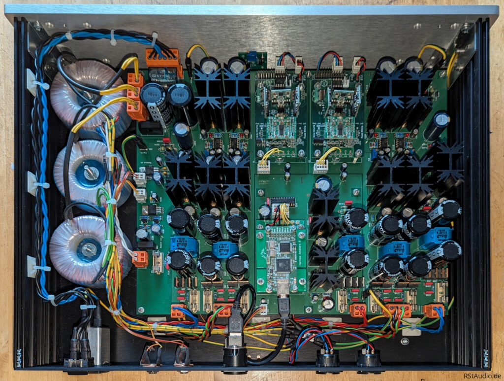
The photo above shows the interior of the DAC. On the left is the circuit board with all the electronic components. On the right, you can see the three toroidal transformers.
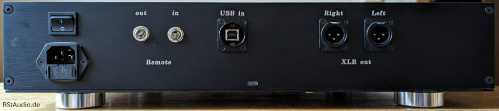
On the left side of the rear panel is the 230V power connection, featuring a socket, filter, fuses, and a switch. To the right of that are the input and output for the remote control voltages. The DAC’s USB input is located in the center. On the right side, you can see the two analog audio outputs. Of course, these are balanced in my setup. I decided against RCA outputs, since I would never use them anyway.