Introduction
December 8, 2015
When I was 15, I became interested in audiophilia and bought my first audio system. Since I had neither the money nor the space for speakers, I listened using a pair of headphones — a pair of Jecklin Float electrostatic headphones. I have very fond memories of these extraordinary headphones, as I spent many wonderful hours listening to music with them.
At the AAA’s Analog Forum 2013, I had the pleasure of listening to a truly high-quality pair of headphones for the first time in a long while: a Sennheiser HD 800. I was immediately captivated by this kind of sound reproduction once again. That’s why I decided to design my own headphone amplifier.
Hardware Description
January 17, 2016
Over the past two years, I have considered many different concepts. In the end, I settled on a relatively simple design based on integrated circuits. Due to my very positive experience with the OPA627 in my crossover, I designed the circuit around this operational amplifier. Since this component is wired as a standard, non-inverting amplifier, many other types can of course also be used.
230V/AC Supply
The 230V/AC power supply is connected to the flat connectors J2 and J3. The ground is connected to J4. Fuse F5 is located directly at the phase input. It is responsible for protecting the entire circuit and should have the lowest possible selectivity. The X2 capacitors C44, C47, and C48 are used to filter the mains voltage. C43, C45, and BR1 filter out any DC components in the mains voltage (C46 is not installed). R15, D10, D11, and C49 connect the ground to the (signal) ground. An external LED can be connected to J5 to indicate the operating voltage.
- Circuit Diagram of the 230V/AC Supply
Power Supply
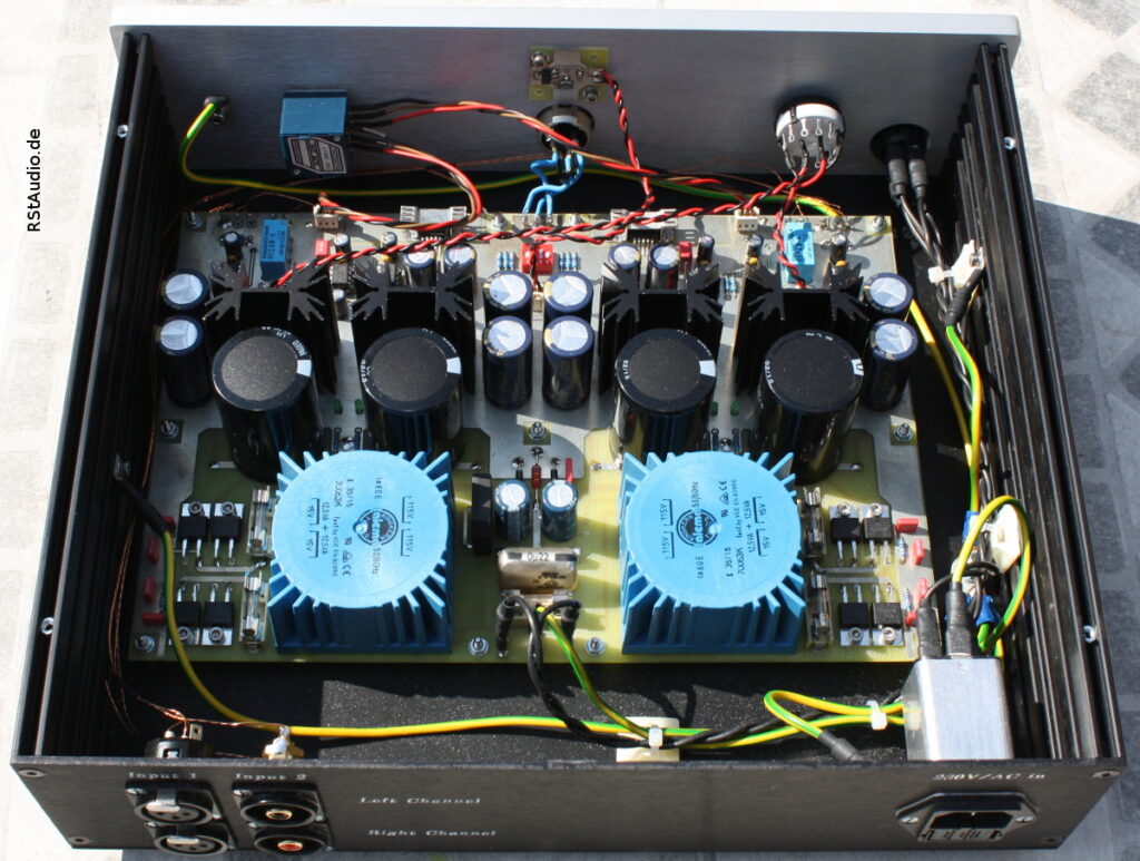
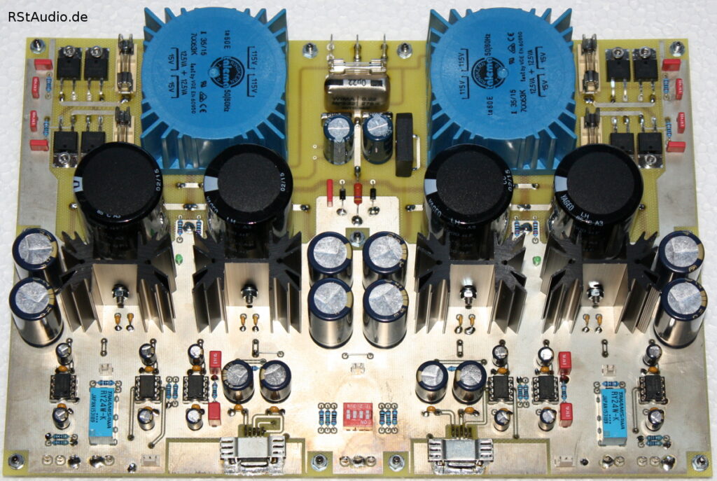
As with most of my designs, the power supply is completely oversized and configured as a dual-mono power supply. However, since a standard headphone with a 6.3-mm plug shares a common ground for both channels, the grounds of the two power supplies are connected to each other. Since both power supplies are identical, I will describe only one channel here.
A 25VA toroidal transformer is used for each channel. Since the transformer is not short-circuit-proof, the secondary-side voltages are protected by fuses. Snubber networks (R1, C1, C2 and R2, C11, C12) are connected to the two output windings, which dampen the resonant circuit — consisting of the inductance of the secondary winding and the reverse-bias capacitances of the rectifier diodes. The two AC voltages are then rectified by a discrete bridge rectifier with ultra-fast soft-recovery diodes.
The balanced operating voltage is regulated to ±15V using two 22mF charging electrolytic capacitors and standard fixed-voltage regulators. I use types from New Japan Radio (NJM7815/NJM7915) here. Four 4.7mF Panasonic FC capacitors are used as output capacitors. LEDs powered by the unregulated operating voltage are used to visually monitor the operating voltage.
- Circuit Diagram of the Power Supply
Amplifier
Since both channels are identical in design, I will describe only the left channel again below.
There are two inputs. An unbalanced source is connected to LK1, and a balanced source to LK2. The balanced input signal is converted into an unbalanced signal by IC6 (INA134). The input signal is selected via Rel1 using an external switch at J6.
The relay is connected to jack J1. One half of an external Alps stereo potentiometer (50 kΩ, logarithmic) is connected here. The potentiometer is used to adjust the volume. The signal voltage is amplified by IC5 (OPA627), and the output current is supplied by buffer IC7 (LME49600). Since the feedback for IC5 is tapped after the buffer, both ICs form a single unit. The DIP switch allows for the selection of different gain factors (here approx. 3 dB, 10 dB, and 20 dB). The circuit around the OP177 (IC8) is a servo controller that ensures a DC-free output voltage. This eliminates the need for a coupling capacitor at the output.
- Left Channel of the Amplifier
- Right Channel of the Amplifier
Installation in an Enclosure
April 11, 2016
As has been my practice in recent years, I used a chassis from Modushop / Hi-Fi 2000 in Italy. I did the machining myself using a Datron M35 milling machine. Since all the components are mounted on the headphone amplifier’s circuit board, the only additional steps are to install the necessary controls and connectors into the chassis.
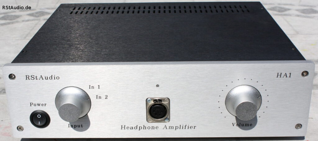
As you can see in the picture above, I installed a 4-pin XLR jack instead of a 6.3-mm jack. I adapted my headphones to use this type of connector so I could run them through a bridge amplifier. Otherwise, the controls are kept very simple, in line with the circuit design. On the left side of the front panel is the power switch, next to it is the rotary switch for the inputs, and on the right side is the volume control. In the center, above the headphone jack, is the power indicator light.
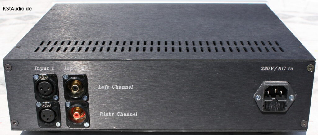
The back panel has a very simple layout. The headphone amplifier requires only two inputs — balanced and unbalanced — as well as the power jack.