
Table of Contents
Correct Connection of the Phase
July 10, 2021
As is well known, a power plug can be inserted into an outlet in two different orientations. In principle, there should be no difference between the two orientations. However, not all devices are designed with a symmetrical power connection. This is particularly true for devices with a two-pin Euro plug (EN 50075, also known as Type C „CEE 7/16“, 250 V/2.5 A). For this reason, it is worth performing the following measurement on your audio devices and plugging the power plugs into the outlet “correctly” according to the measurement results.
- All connections between the audio device being tested and other components of the audio system must be disconnected. Only the power cord itself should remain connected.
- Using a standard digital multimeter, measure the AC voltage between the outlet’s protective conductor and a ground point on the audio device. The easiest way to do this is at the outer pin of an RCA plug.
- After taking the first measurement, turn off the device and rotate the power plug in the outlet 180 degrees. Then turn the device back on.
- The AC voltage is now measured again as described in step 2.
- Measuring the lower voltage indicates the correct audio position of the power plug.
As you can see, you don’t need an overpriced phase meter from an audio store. All you need is an inexpensive digital multimeter from an electronics store. The nice bonus is that you can use this meter to perform a variety of other measurements as well.
DC filter for the 230V/AC Mains Supply
July 10, 2021
I first came across a description of a DC filter on the website www.saque.de.
I first experienced the sometimes “significant” changes that occur when using DC filtering in the 230V/AC power supply of an audio device with my small Zen power amplifier. Since then, I have installed the filter described below in every power supply line of my DIY audio components.
The physical effect of this filter is easy to explain:
If you analyze the voltage from the outlet more closely, you may find some alarming results, depending on your geographic location and the time of day. The voltage is not always sinusoidal, and it also contains DC components. It is precisely these DC components that are at issue here. They cause pre-magnetization of the transformers in audio equipment, which can have a significant impact on the sound quality of the device. The filter described here “blocks” these DC components, thereby preventing the negative effects of pre-magnetization of the power transformers — so there’s absolutely no voodoo involved!
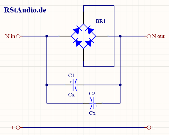
The circuit diagram for the DC filter described above is shown in the figure. The capacitors (C1 and C2) block the DC component, while the diodes in the bridge rectifier (BR1) ensure that the voltage across the capacitors cannot become too high (in this case, two diode paths, which corresponds to approximately 1.2V). I have connected two capacitors in anti-parallel, which adds their capacitance values together. However, one must accept that during one half-cycle of the mains frequency, one capacitor is always reverse-biased. In my experience, this works well as long as the maximum voltage is limited to 1.2V and the capacitors have a voltage rating of at least 25V. If you want to play it safe, you should connect two capacitors in series (either both negative terminals or both positive terminals connected together), thereby creating a bipolar capacitor, although the capacitance is halved.
When dimensioning the filter, it is important to ensure that the voltage across the capacitors remains below the diode voltage at maximum current. I will use my Zen power amplifier as an example to demonstrate the sizing process.
The transformer has 2× 15V / 5.7A on the secondary side. This results in a power output of
This results in a current on the primary side (assuming the transformer is lossless) of
When two diodes are connected in series, the resulting voltage across the capacitors’ impedance must be less than 1.2V. This results in
From
this gives the capacity
However, if you use a 1900μF capacitor, you will have no margin for the DC offset at the rated current calculated above. The reason is that the voltage drop across the capacitor’s impedance is so high that the diodes in the bridge rectifier turn on. For this reason, a larger capacitance must be selected. In my Zen power amplifiers, I used 2 x 10,000μF. As a good guideline, you can use the following rule of thumb:
per 100VA ≈ 10000μF
This sizing results in a voltage drop across the capacitor’s impedance XC of
This results in a blocking voltage of approximately 1V (with two diodes in series) for the DC component of the 230V/AC voltage.
For my Zen power amplifiers, this ultimately results in a value of
Snubber Network
April 21, 2014
When a transformer is used in conjunction with a rectifier—which is the case with almost every power supply—a high-frequency oscillation occurs in the DC voltage. There are some excellent articles online that describe this effect and also derive theoretical and mathematical models showing how to design a network that dampens this oscillation. Unfortunately, these calculations require precise data on the transformer and the rectifier diodes. Determining this information is not always easy.
On diyaudio.com, you’ll find a very interesting discussion about determining network parameters using a test circuit. A detailed description of the circuit is available for download as a PDF file in the first post.
Simple, no-math transformer snubber using Quasimodo test-jig
I built the measurement circuit and installed snubber networks in my XA30.5 replica for the first time. The following two images show the measurement of the transformer without (left) and with (right) a snubber network adapted for a secondary winding.
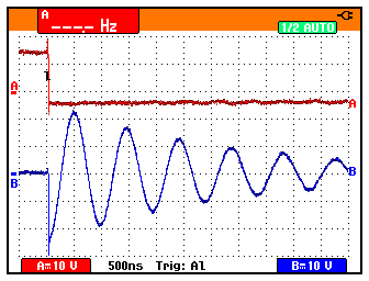
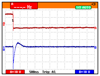
Channel B (shown in blue) displays the oscillation in a secondary winding of the transformer. Note the horizontal resolution (500ns) and the vertical resolution (10V).
These days, I never build an audio power supply without snubber networks. They are an integral part of all my current circuits.