!!! PCBs Available !!!
Table of Contents
Introduction
February 10, 2020
An electrostatic loudspeaker consists of two stators and a moving diaphragm that is mechanically clamped between them. For this simple principle to work, the diaphragm must be conductive and biased with an electrical voltage. The stators must then be driven in antiphase with the music signal so that the diaphragm oscillates in time with the music. Unfortunately, this setup does not work at low voltages, since the diaphragm requires sufficient space for deflection to produce a noticeable volume, and air is a good insulator.
Consequently, the diaphragms of the 57 Quad ESL are driven by approximately 1,500V/DC (treble) and approximately 6,000V/DC (bass). Since the audio signal requires significantly higher amplitudes than standard power amplifiers can provide, this signal is stepped up by a transformer.
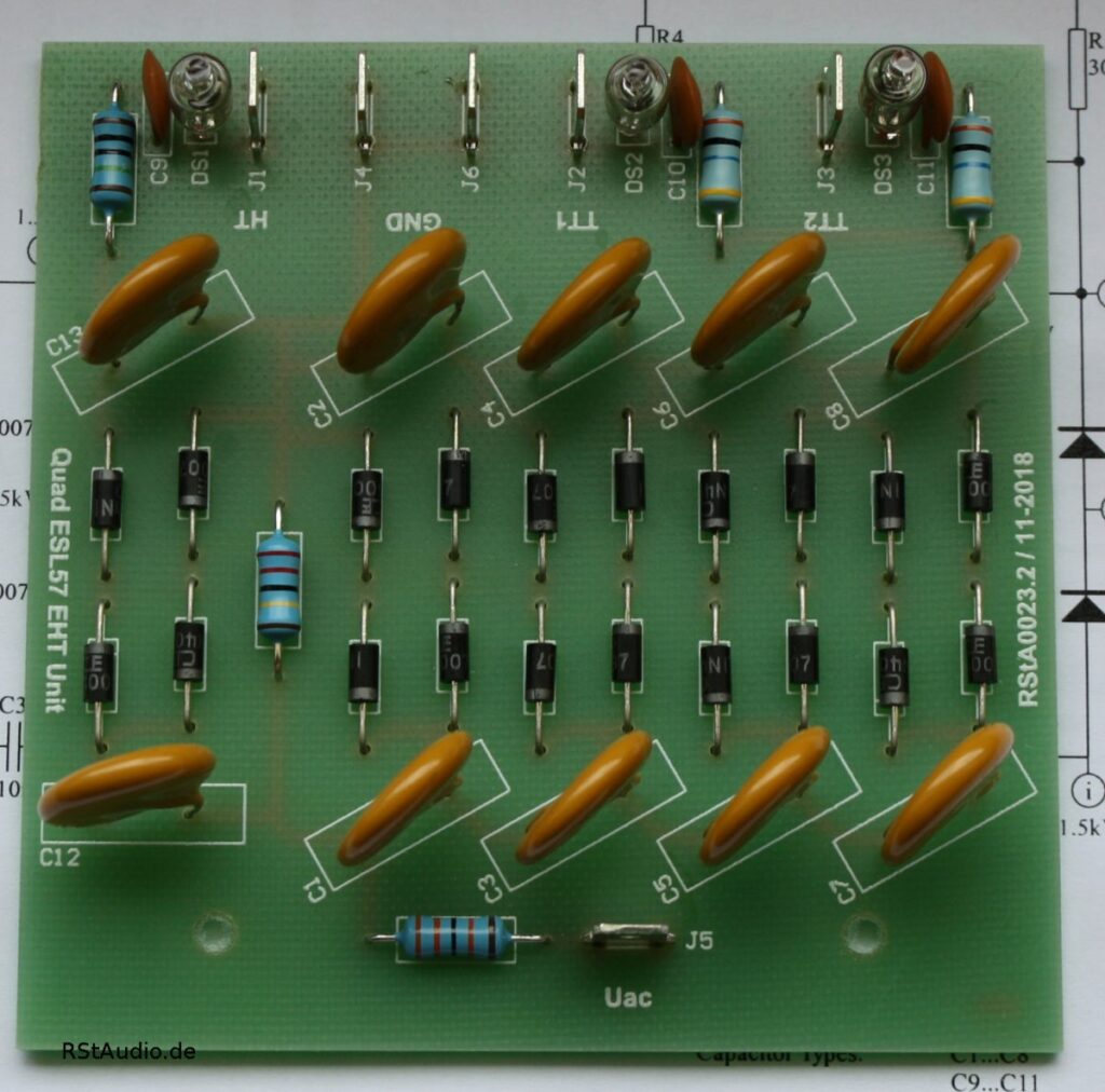
To generate the high voltages required for the foils, a mains transformer with connected voltage cascades in a Greinacher circuit is used. The lower high voltage of the high-frequency signal is tapped after the first cascade.
Over the years, the diodes in the Greinacher circuit “wear out”, causing the DC voltages across the foils to drop noticeably. The deflection of the foils decreases. For this reason, when overhauling the Quads, it is absolutely essential to replace at least the diodes in the cascade as well. That is exactly what I did when I refurbished my Quads in 2011.
When I refurbished my Quads in 2020, I decided to build and install a completely new EHT unit.
Circuit Description
May 16, 2021
The goal of this design was to avoid encapsulating the cascade in wax, as is done in the original, while still ensuring functional safety. Additionally, I did not want to tap the high-voltage signal from the bass cascade for the tweeter. Instead, the tweeter was given its own cascade. At the output of the cascades, there are also separate networks consisting of a resistor, capacitor, and glow lamp for each individual foil.
These ideas are not new and have already been described elsewhere. However, I consider them to be very good ideas, which is why I wanted to incorporate them into my implementation of the Quad EHT Unit.
The original network is said to have been developed by Anders Enquist. Unfortunately, I couldn’t find a direct link to it, but I did come across a description of the network’s advantages in the extensive documentation on the Quad that I’ve collected over the years:
The idea of it is that the neon lamp isolates the panel from the EHT supply until there is a voltage across the capacitor which is high enough to flash the neon lamp. This takes some 20 volts or so. When the lamp flashes a fraction of a second the panel is charged. Apart from improving the sound, it’s a health inspection as well. If everything is going well you should notice a short flash from the lamp now and then. If it flashes all the time there is a short circuit. If, on the other hand, it doesn’t flash at all, there is a component break down in which case the panel connected will be dead. Soundwise, this tweak will make the bass leaner but with better impact. Sounstage depth will increase too.
… This bring a considerably tighter bass. You may feel the mid-range opens too, but I believe that it is a subjective side-effect of better bass definition. …
Anders Enquist
As you can see in the picture above, the EHT unit is still connected to the transformer’s 610V/AC winding. To better adapt to the existing voltage conditions, all of my quads are now connected to the 590V/AC tap. Combined with an upstream RStAudio Quad ESL Voltage Regenerator, this provides stable and optimal voltages to the foils.
However, my requirements for the circuit board come at a cost: the original size cannot be achieved, and as a result, the circuit board must be mounted differently. We decided to screw the board onto the mounting strips attached to the transformer. To do this, you need to drill two holes and mount the circuit board using insulating spacers. I was initially concerned because securing it at only two points seemed insufficient to me, but in practice, this has proven to be adequate.
Printed Circuit Board
March 30, 2024
I ended up getting quite a few inquiries about the circuit board, so I decided to have a small batch manufactured. If you’re interested, please feel free to contact me using the form below.
Please make sure you enter your email address correctly. Otherwise, I won’t be able to send you a reply. You can rest assured that I will respond to every inquiry.
Unfortunately, the contact form isn’t working for some users. If that’s the case, please send me an email at
info[at]rstaudio[dot]de
Please replace the text in the square brackets as appropriate (SPAM protection).