Table of Contents
- Introduction
- Matching the Semiconductors
- Analog Power Supply
- Preamplifier Board
- A First Operation of the Preamplifier
- Volume and Gain Control
- Input Selector
- Microcontroller Board
- I²C-Bus Relay Driver Board
- Relay Power Supply
- Description of the Software
- The Complete Prototype
- Remote Control
- Building the Case
- Wiring
- Updates & Improvements
- Clones of my Aleph P
Introduction
2006/02/23
Shortly after I have decided to build the Aleph JX power amplifier, I came to the conclusion to build a whole system with the Aleph philosophy. I started to build the Aleph P Ver. 1.7 preamplifier in parallel with the power amp. It is my third DIY preamplifier and therefore he get’s the name VV III (Vorverstärker III – the translation means preamplifier 3). I choose the Aleph P in the 1.7 version and I worked on this project with the highest priority, so that I could finished the preamplifier as the central of the audio chain at first.
The preamplifier circuit and the analog power supply is taken from the original schematics with nearly no changes. Because I always build dual mono systems I used two analog power supplies in difference from the original design. The control electronic is based mainly on my ideas, but if you look at the possibilities you have for a controller with this hardware there is not so much to do and therefore you find a lot of things also in the control of the X series preamplifiers from Pass Labs.
A lot of informations for audio circuits from Nelson Pass you find on Pass DIY and diyAudio.com.
Matching the Semiconductors
2006/02/23
I need in both halfs of the preamplifier circuit transitors with nearly the same electrical behaviours. Therefore I bought 50 IRF610 and also 50 IRF9610 from the supplier Conrad. I expect that they came from one wafer and have similar physical measurement results.
I took the article How To: Matching Devices from Nelson Pass and try to select pairs in the way he discibed there. The measurement circuit I used you can find here.
I used a 12V/7Ah battery as the voltage source and I controlled the voltage during the whole measurement. To measure the Gate-Source voltage I used the Agilent 34401A with 6 digit resolution.
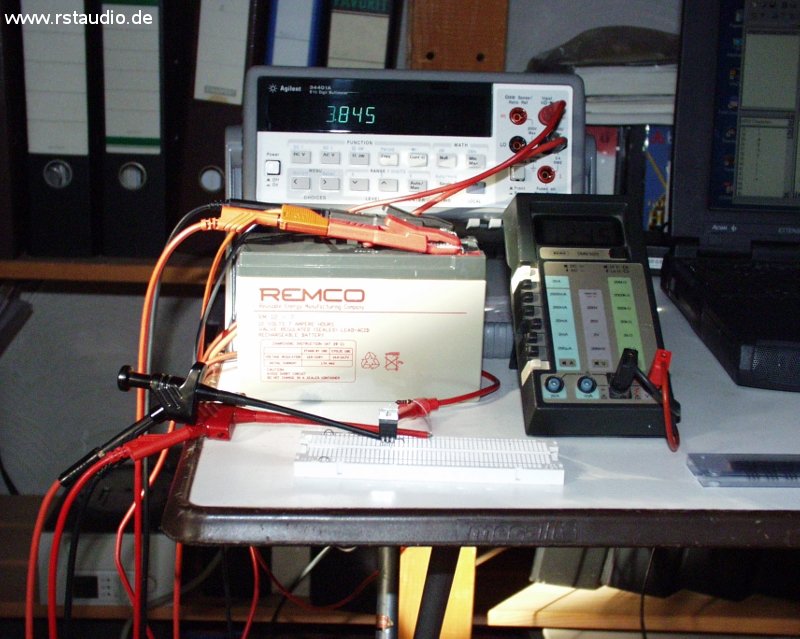
Measurement Equipment for Matching the MOSFET’s
The temperature has a very high influence on the measurement results, therefore I wait a longer time (up to 5 minutes) so that the MOSFET’s reach a stable operating point. I also tried to isolate the transistor from air flow. The MOSFET’s with a maximum difference of 1mV were possible candidates and I measured them a second time in the differential mode (see above).
Analog Power Supply
2006/02/25
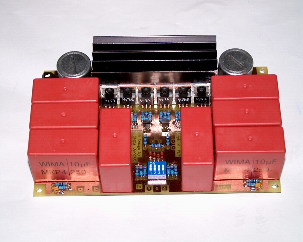
The analog power supply regulator circuit is not changed from the original design. But I used a dual mono construction with a transformer and a power supply board per channel. The transformers have 2x30V / 50VA, the secondary windings are series connected. The first capacitor after the rectifier has 2200μF/100V and after the source follower I use a C-R-C combination (1000μF – 3.3Ω – 2000μF – were the 3.3Ω and the 2000μF (2x 1000μF) are sitting on the preamplifier board). At the input there is a 4 pin connector with the possibility to bridge the secondary windings. A 3 pin connector is used at the output with 2 pins connected to analog ground. One is used to connect the ground with earth via one half of a power rectifier (two diodes anti-parallel).
- Schematic of the analog power supply
- Top Overlay of the board
The picture shows the Rev. 1 of the board.
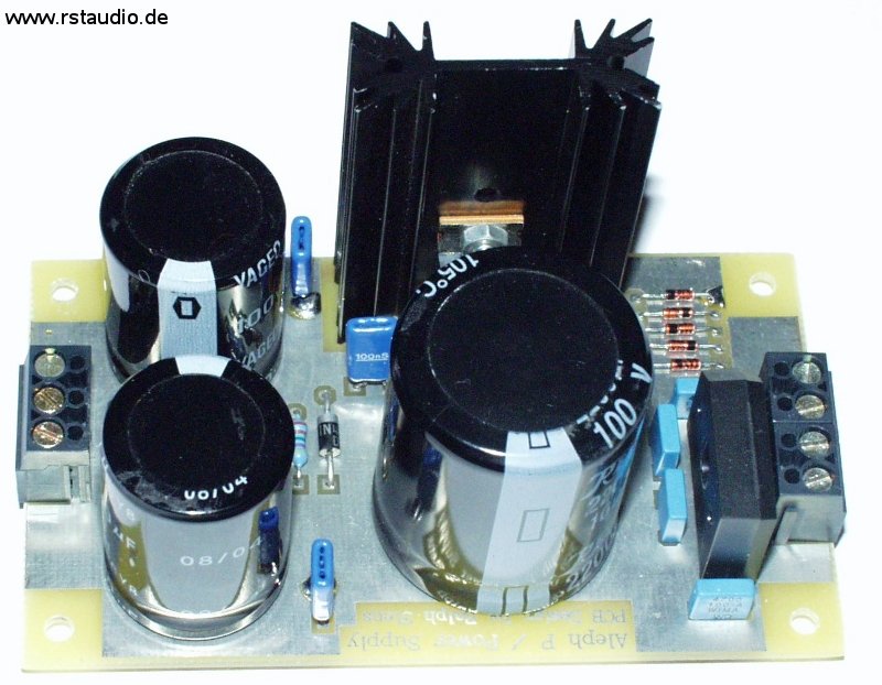
Analog Power Supply Board
There is no change of the schematic in the Rev. 1. I’ve added at the transformer input 2 connectors (which are wired together) for the series connection of the secondary windings (e.g. a 2x 30V transformer). At the output you find a second Ground connector. Here you can easily connect the ground with earth (see below)
Preamplifier Board
2006/02/25
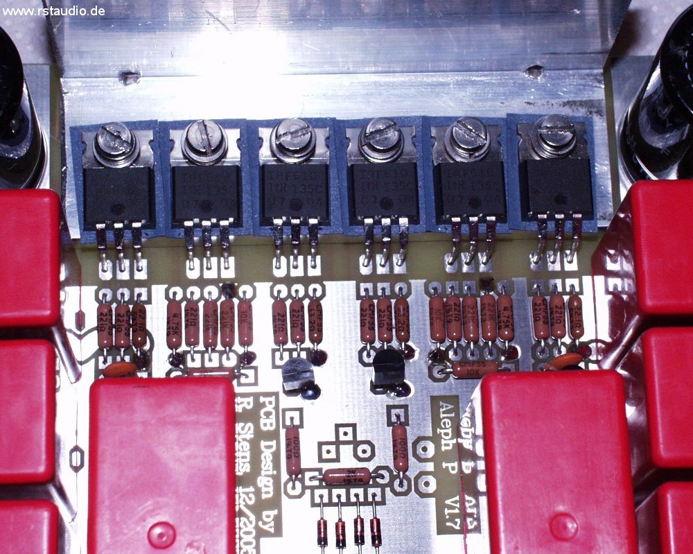
The Aleph P preamplifier shown here is the version 1.7 with the four active current sources. I use the original MOSFET’s from International Rectifier (IRF610 and IRF9610) and Wima 10μF/160V MKP4 coupling caps. They need most of the available room on the board. All 6 MOSFET’s are placed on a aluminium holder to keep the same temperature on all transistors for a thermal balance. I used BC550C / BC560C for the bipolar transistors in the current sources.
Both halfs of the amplifier were coupled with resistors (R51, R66, PGain, PG). With the value of them you can influence the “inner” gain of the circuit. In the original design you find here the potentiometer. On my board there is the possibility to use a variable resistor or to connect an external one at J5a and J5b (potentiometer or switchable resistors – see below). For the first operation I used a variable resistor with a fixed gain.
Like the original design you find a four pole DIP switch at the input. Here one can switch a damping factor for the incoming signal.
For the AC coupling of the preamplifier I use 10μF/160V MKP4 capacitors from Wima. The 6 MOSFET’s were mounted on a kind of L form heat sink. With these heat sink all transistors have the same temperature.
- Schematic of the Aleph P preamplifier
- Top Overlay of the board
You see one channel with a variable resistor for the gain adjust (blue part in the middle of the board).
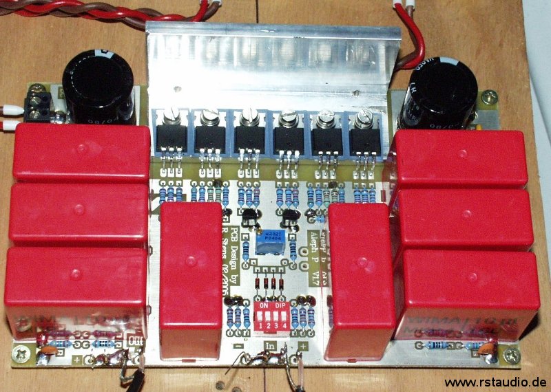
Aleph P Ver. 1.7 Preamplifier
A First Operation of the Preamplifier
2006/02/23
After finishing the preamplifier boards and the two analog power supplies I was able to put them into operation for the first time. To control the volume I used a normal 10kΩ variable stereo resistor at the output of the preamp. The gain was controlled with a variable resistor on the board. I used my single ended CD player as the source and the single ended Zen amplifiers to drive my Quads. The negative input of the preamp was connected to ground.
I was shocked from the results of this preamplifier. In the past I have the opinion that my little Zen power amplifiers are the bottleneck in my audio system and I thought that I have a nice tube based preamplifier – but the Aleph P teached me something else.
Let me say it in short words – I’m totally enthusiastic about the results !!!
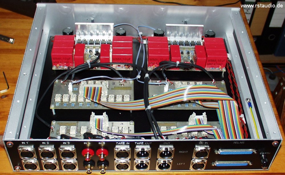
You see on the picture the complete first prototype. At the back there are the two 50VA transformers. In front of them the analog power supplies and the preamplifiers. At the vertical board in front you find the input and output connectors and the variable resistor to control the volume.
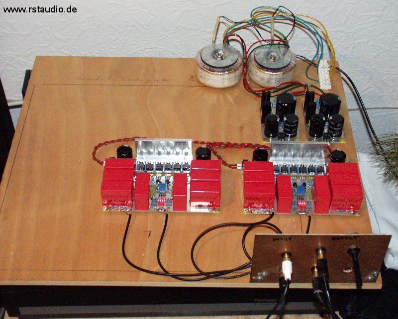
First Operation of the Preamplifier
Volume and Gain Control
2006/02/25
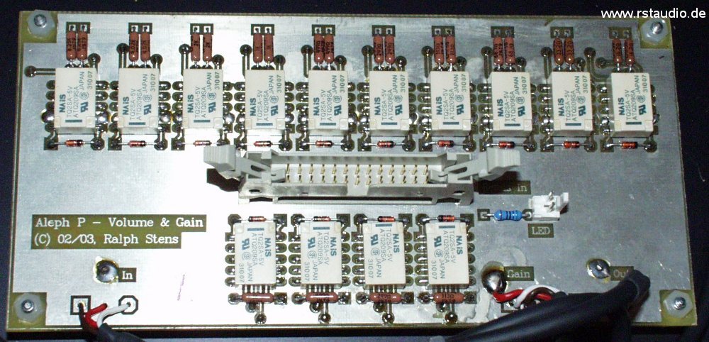
The design of the volume control is more or less like that of the original Aleph P, but I changed it from 8 to 10 bit. As a result I get a damping factor of arround -60dB. I used 1% metal film resistors which I have matched under 0.1% with an Agilent 34401A. The values in the volume control are 62Ω, 124Ω, 249Ω, 499Ω, 1kΩ, 2kΩ, 4.02kΩ, 8.06kΩ, 16kΩ and 32.4kΩ.
A small disadvantage of the 10 Bit divider is, that the values of the biggest resistors (16kΩ and 32.4kΩ) are in the region of the input resistance of power amplifiers. Therefore you have to consider the input resistor of the next device (e.g. a power amplifier) in the calculation of the damping factor (dB).
There are also 4 resistors for changing the gain of the amplifier. The resistors are 249Ω, 499Ω, 1kΩ and 2kΩ. The resistors are in parallel and therefore there are 15 different values switchable. Also this resistors are matched within 0.1% with the Agilent 34401A.
The complete schematic consist of the voltage deviders with the gain control and the relay circuit.
- Top Overlay of the board
I use 1N4148 for the diodes across the relay coils. The current is low enough not to use the 1N4001 witch is selected in the schematic.
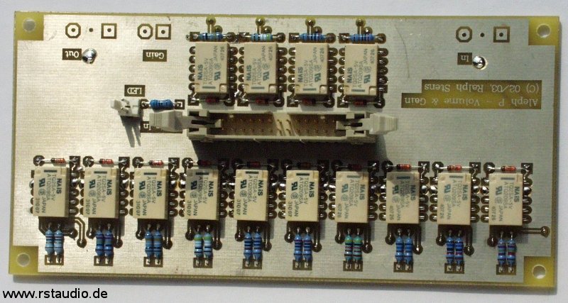
Board for the Volume and Gain Control
Input Selector
2006/02/25
The input signals were switched with relays of the same type like the volume and gain. This circuit consist of 5 differential inputs and one differential tape loop. There is one more relay on the board with which the negative signal path of the differential inputs can connected to ground. You can use this relay to connect a single ended input signal to one input channel without the need to wire the negative differential input to ground.
- Schematic of the Input Selector
- Top Overlay of the board
I also use here the 1N4148 for the relay coils (see above).
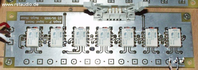
Board for the Input Selector
Microcontroller Board
2006/02/25
A microcontroller is responsible for the control of the whole preamplifier. The user has two rotary encoders with switch to operate with the preamplifier. A display with 2 rows and 20 columns gives all informations to the user. There is also a remote control input available.
I use the AT89C51RC2 from
Atmel because he has 32kByte flash ROM and 1kByte of internal RAM. The I²C-bus EEPROM 24LC64 is used to store the user configurations and inputs. PF2 is the external connection for the I²C-bus and LK1 is used to connect an IR-detector from the TSOP17xx family. PF1 is the connector for a standard LC-display with a Hitachi interface and background light. P1 is used to change the contrast of the display. The controller can use Q1 to switch the background light on and off.
This circuit is the input of the two rotary encoders. R6…R11, C8…C10, IC5A…IC5C is the debouncing circuit for the first and R12…R17, C11…C13, IC7A…IC7C for the second encoder. IC8A, IC8B (74HCT123), IC6D (74HCT86) and IC5D (74HCT14) formed an interrupt signal when the second rotary encoder is moved. At LK7 and LK8 you can connect switches (not used). The debouncing circuits for this switches are R20…R23, C16…C17 and IC7E…IC7F.
With Q2 and Q3 the microcontroller can switch the relais REL1 and REL2. The controller is able to control two 230Vac lines with this two relays. At J10 you can connect a LED which is in on status when the 5Vdc voltage is available. LK1 is the connector for the 230Vac of the power supply and the circuits F1, TR1, BR1, IC4 and C4…C7 are building the power supply for the microcontroller itself.
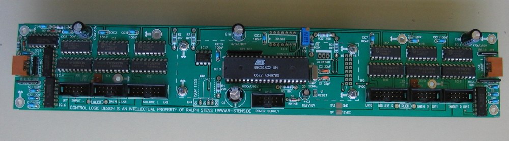
- Top Overlay of the μC board
The picture shows the μC board with a textool socket for the controller. I use the manual potentiometer for the contrast variation of the display.
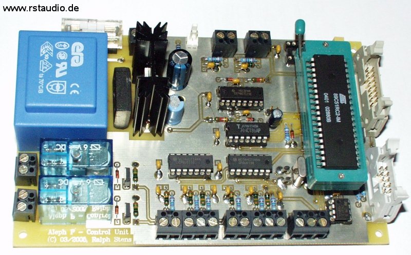
Microcontroller Board with Textool Socket
I²C-Bus Relay Driver Board
2006/02/25
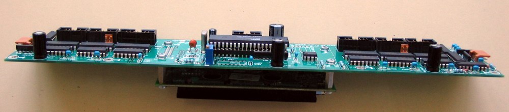
The complete preamplifier has 42 relays to control the audio signal. Because I want to have boards not bigger than 160mm x 100mm I’ve build this driver board outside the μC board. The communication between the microcontroller and the driver circuits is done with an I²C-bus.
PF1 and PF2 are the input connectors with the I²C-bus and the power supply for the I²C-bus ports PCF8574 (IC1, IC3, IC5, IC7, IC9, IC11). The I²C addresses of the ports are fixed. The port devices are not able to drive the relays and therefore I use the open collector Darlington drivers ULN2803A (IC2, IC4, IC6, IC8, IC10, IC12). LK1 is used to connect the power supply of the relays. To have a power supply of its own for the relays gives the possibility to use another voltage for the relays as the voltage of the microcontroller board.
PF3 and PF4 are the connectors for the volume / gain and the input board (left and right channel). You must divide the 40 pin ribbon cable up to connect this board. In this design the control and audio electronic use different frames and I connect 2 37 pin Sub-D with PF3 and PF4.
- Schematic of the I²C-Bus Relay Driver
- Top Overlay of the Board
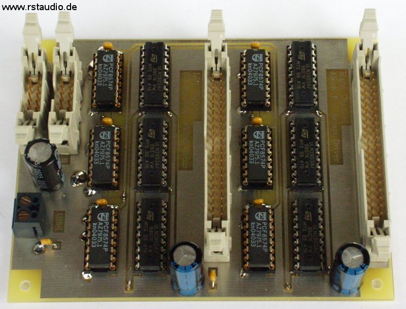
I²C-Bus Relay Driver Board
Relay Power Supply
2006/02/25
The power supply of the relays used the 3A regulator LM323 (IC1). The current is enough to switch all relays at one time (which is impossible in a realistic mode). Also the 16VA transformer and the 8A bridge rectifier are big enough. The extra fuses F2 and F3 are used for the primary windings of the audio transformers (LK2 input, LK3 and LK4 output). A connector for an LED is also available (J1).
- Schematic of the Relay Power Supply
- Top Overlay of the Board
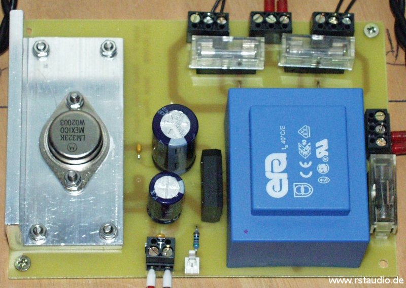
Relay Power Supply
Description of the Software
2007/06/05
During the description of the microcontroller board I made a short notice how to operate the preamplifier. The user have two rotary encoders with switch to make changes. An LC-display with 2 rows and 20 columns is used to give the user all informations.
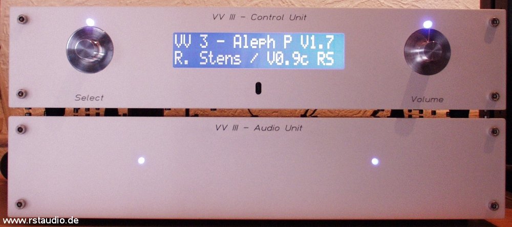
After the preamplifier is switched on you see for a longer time the welcome display. During this time the user isn’t able to make any changes. The time (here 60s) is used for the stabilisation of the analog power supply. After this time the last input is automaticaly selected and also the volume and gain is switched (see below). Than the main screen is written on the display, the preamplifier is in its normal operation. In the first row you see the active input and in the second row the volume (separate for both channels).

Main Display Informations
The rotary encoder for the volume use one external interrupt of the controller. At every time and in every menu (see below) the operator can change the volume. When you reach the lower or upper end of the volume selection no more changes were made (the rotation is endless).
A short push on the volume encoder select the mute function. If you push these button longer than 2.5s the preamplifier goes in its stand by mode. The AC voltage of the relay power supply and the analog power supplies (see below) is switched off. In this mode the LED’s of the analog power supplies, relay power supply and the background light of the display is switched off. Only the LED of the μC power supply is active. A short push on the volume encoder let the preamplifier come back in its normal mode.
With the select rotary encoder the inputs were switched. The whole configuration of the actual selected input is used (see below).
A push on the select encoder let the controller go into the configuration menu. The following items exists :
| Tape Input | Tape Monitor ein- oder ausschalten tape monitor on or off |
| Gain | die „innere“ Verstärkung des Aleph P wird geschaltet the gain of the preamplifier is switched |
| Mute | der Ausgang wird stumm geschaltet the output is switched off |
| Balance | Balance Einstellung balance input |
| Start Volume | Vorgaben für die Volume und Gain Einstellung beim Einschalten the volume the preamplifier use direct after turn on |
| Write Volume | Ausgabe des Volume in dB oder als fortlaufende Nummer the volume is written on the display with a number or the damping factor in dB |
| Input Config. | Konfiguration der Eingänge – Name, Pegel, SE/Diff. configuration of the inputs – name, volume, SE/diff, active/inactive |
| Stand By | analoge Spannungsversorgung abschalten (ja / nein) analog power supply switchable |
| Display | Einstellung des Kontrastes contrast of the display |
| Heat Up Time | Einstellung der Stabilisierungszeit beim Einschalten waiting time for the power supply stabilisation after power on |
| Software Version | Ausgabe der aktuellen Version der Embedded Software output of the current version of the embedded software |
| Delete Memory | alle gespeicherten Parameter löschen delete the EEPROM |
| Quit | Menü verlassen exit the menu |
With the select rotary encoder you choose the wanted menu item and when it is written on the display you activate it with a push on the select encoder. In the menu item you choose the wanted configuration once more with the rotary encoder and select it with a push. After that the program goes directly back to the normal operation mode.
Tape Input
In this menu you can switch the tape monitor input on or off. In the first row of the display you see the information that the tape is active. Also written is the active input (only with its number and not with its name). This is the input channel you can record from. Even with an active tape monitor you can switch the normal input channels with the select rotary encoder.
Gain
With this menu you can select the “inner” amplification factor of the preamplifier with the selection of RG. There exist 16 possible values, but I use not all because the differences between some are very small.
Mute
With mute you switch the output off. In reality all volume relays were unselected and connected to ground. As a result there is no active connection between the outputs of the amplifier an the Volume / Gain board. When mute is again switch off the same volume as before is choosed.
Balance
There exist no real circuit for a balance between both channels. Here the balance is realised with different volume values in both channels. You can change the values only up to ±15.
Start Volume
With this menu you can define the volume and gain values directly after the run up. At first you have to choose between last and fixed. If you have selected last the last values directly before the shutdown were used. If you prefered fixed, predefined values for the volume and gain were used. You have to program both values with the select rotary encoder.
Write Volume
The actual volume is written on the display during the normal operation (second row). Here the operator can switch between the output of a number (from the lookup table – beginning with 1 at the lowest volume) or the damping factor in dB. For the correct values of the damping factor you have to include the input resistance of the following device (normally a power amplifier). The Zen V4 amp has for example 47kΩ.
Input Config.
This is the most complex menu item for the configuration of the preamplifier. You can give an input channel an individual name (up to 16 characters), you can choose wether the input channel is single ended or differential, you can make a volume and gain correction and you can hide the channel. After selecting the menu you must at first select which input channel you want to config (Input 1 … Input 5, Tape). Then you get the following sub menu :
- Name
- Diff./SE Input
- Level Correction
- Gain Setting
- Input on/off
- Quit
As I write before, you can give the input an individual Name. You get the wanted letter with the rotary encoder and select it with a short press on the button of the select rotary encoder. After the input of all letters you select the whole name with a longer press (> 2.5s) on the button. Then the program goes back to the input sub menu.
With the Diff./SE Input menu you can switch an input between single ended or differential. In the single ended mode the negative channel is automatically switched to analog ground.
In the Level Correction sub menu you can select an individual offset of the volume to minimize the volume difference between the input channels.
The Gain Setting gives you the possibility to set the inner gain of the preamplifier individually for every input channel. With both parameters you are able to minimize the volume jump between each audio source.
With the Input on/off sub menu you can activate or deactivate an input channel. This is an elegant methode to eliminate an input channel without a connected source from the input selection.
Quit is used to leave this sub menu.
Stand By
In the Standy By mode the controller is furthermore active, but the relay power supply and the LCD background light is switched off. The user can choose in this menu wether the analog power supply is also switched off or not. The advantage of leaving the analog power in operation is that the preamplifier electronic is all the time in a stable thermal operating point (of course you need more energy).
Display
The operator can change the contrast of the display in this menu. The hexadecimal value of the digital resistor is written on the display and you see the changes immediately. You leave the menu when you press the select switch.
Heat Up Time
Here you have to select two timing values in seconds. The first time – Cold Time – is the time the preamplifier needs to go into his normal operation mode after you switch on the 230Vac. The second time – Warm Time – is the waiting time after a stand by (without switching the analog power supply off – see above).
Software Version
The current software version is written for 10 seconds on the display. After that the program goes automatically back to the main screen. After the software version number you find two characters (up to now only RS) which gives the information about the individual look up table which is compiled in.
Memory Delete
After selecting this menu the user is asked wether he wants to do this operation or not. The answer no is the default. If the user select yes all values stored in the EEPROM were erased. You have than the status like the first switching on. If you choose no you leave the menu without an action.
Quit
You can leave the configuration menu without any changes with this menu item.
For the contrast of the display the design has two possibilities – a variable or a programmable resistor. If the preamplifier use the programmable resistor there is the danger that the momentary value let the written output unseen and than the operator is unable to change the contrast (because he needs the output of the display). When the preamplifier is in normal operating mode (LED’s at the audio module are not blinking, all relays were switched) a longer push (more than 2.5 seconds) on the select rotary encoder brings you in the parameter menu like above, but change also some parameters to a default value – you should immediately have something readable on the display.
I never used the digital variable resistor !!!
The Complete Prototype
2006/02/23
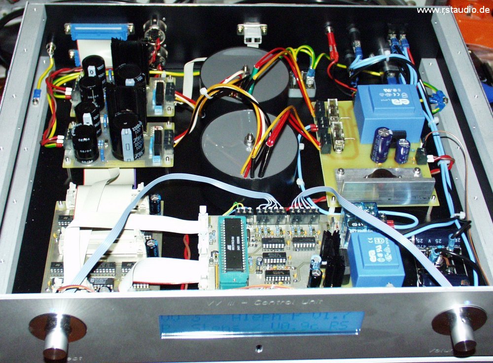
After all circuits and the software are finished I was able to put all into operation and therefore I change the first prototype (see above). I don’t look at a clean wiring with audio cables, all I want to have is an operation of all parts of the preamplifier. The results are excellent – no humm, no noise, …
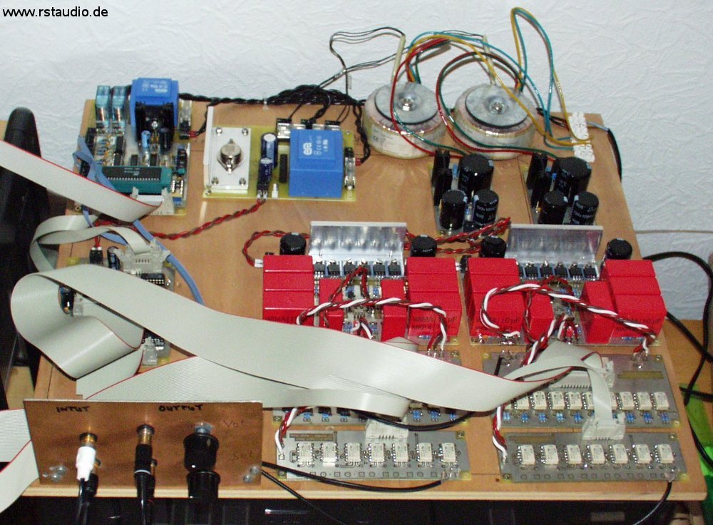
Complete Prototype
You can’t see the display on the picture above, all you can see is a ribbon cable going out of the picture on the left side. For this reason here is also a picture of the display with the start up screen.
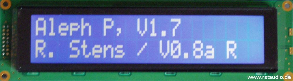
Display of the Prototype
Remote Control
2006/02/23
The remote control is based on the original schematic of the Aleph P and makes also use of the SAA3010 from Philips. Because of the different user interface and the plan to use this remote control also for my D/A converter there are changes in the circuit. I use more switches with a different coding and also the base address of the RC5 code is not the same (address 7 – experimental).
The remote control must have the same functionality like both rotary encoders with their switches. With the exception that the switch of the volume is only used for the Mute function. For the Aleph P I need 6 switched. The D/A converter used one rotary encoder for the user interface. At least the remote control need 9 switches.
I don’t need a remote control for myself. This is the reason why I havn’t build the hardware up to now and why you don’t find schematics here. The software routines are available, but I can’t say anything if they are working or not.
Since I had started to present my Aleph P Clone on the Web a lot of DIY’ers all over the world asking for a remote control. Because I don’t need it and my little amout of free time which I prefer to spend for my own projects I never start to implement it (see above). At least Daniel M. started a small project and has build a circuit to control the volume via remote control.
I made some minor changes to the software. An active low signal with a lenght above 5ms at the free pin P3.4 increase the volume with one step. The same kind of signal at pin P3.5 decrease the volume. With this new feature Daniel starts to develop his hardware. Here is a short description of the function from him:
…
The controller is an Atmel Tiny 25, I don’t change the fuse bits, the brown out detection is activated (I use 2.7V).
This is the function:
RC 5 Code.
Address 16 is in use.
With command 61 or 12 a 4 second high pulse at PB2 is generated (Standby On Off).
With command 13 a 30ms pulse at PB2 is generated (Mute).
After pushing one of these buttons at the remote control you have to release that command to get the possibility to start a new command. This is to get no double signals by pressing one button (this is not used for the volume).
Command 16 increase the volume.
Command 17 decrease the volume.
…
Below you find the circuit and a photo of the prototype:
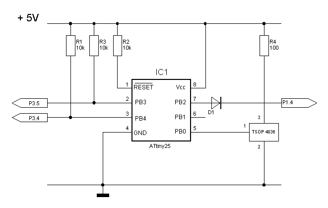
Daniel’s Remote Control – Circuit
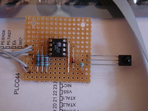
Daniel’s Remote Control – Photo of the Prototype
If you are interested to build this circuit please contact (email address is alienate):
meldano[att]web;de
Building the Case
2006/05/15
I used the X1 preamplifier from Pass Labs as an example for the design of my case. The biggest difference between the X1 and my case are the complex front of the X1 and the use of two rotary encoders in my design. But like the X1 I also use two cases for the complete electronic :
- Control Unit
- μC Board
- I²C-Bus Relay Driver
- Power Supply for the Relays
- 2x Transformers for the Analog Power Supply
- 2x Analog Power Supply
- Rotary Encoders & Display
- AC Power Connectors
- Connection between Ground and Earth
- Connectors to the Audio Unit
- Audio Unit
- 2x Preamplifier
- 2x Volume and Gain Control
- 2x Input Selector
- all external Audio Connectors (XLR & Cinch)
- Connectors to the Control Unit
I design the cases with the program Frontplatten Designer from the German company Schaeffer AG.
- Front of the Audio Modul
- Back of the Audio Modul
- Front of the Control Modul
- Back of the Control Modul
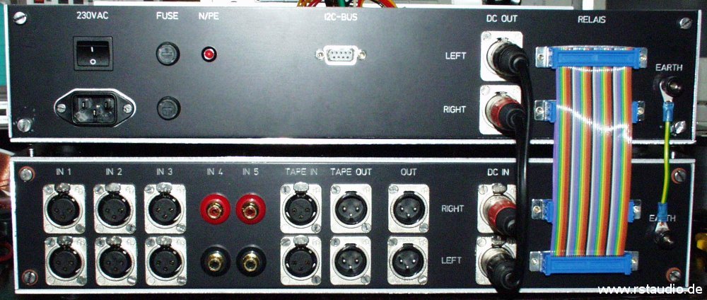
You see here the front and back of the empty audio modul without the top cover. All needed connectors are included at the back.
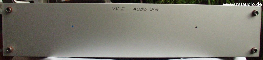
Front of the Audio Modul
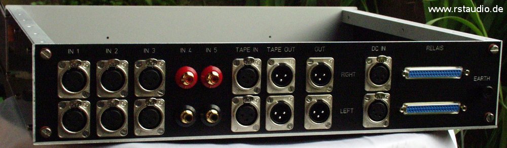
Back of the Audio Modul
And here you see the case of the control modul. On the front there are the holes for the rotary encoders, the display, the LED’s and the IR receiver. At the back you find the holes for the AC and DC connectors, the Sub-D for the relais, an earth connector and a Sub-D for the I²C-bus.
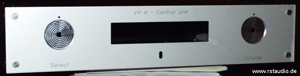
Front of the Control Unit
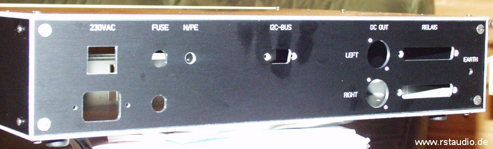
Back of the Control Unit
The following is an extra photo from one of the two knobs. To produce them was not simple, but the result is very, very nice. Many thanks to Enrico B. who has spend parts of his weekend to produce them.
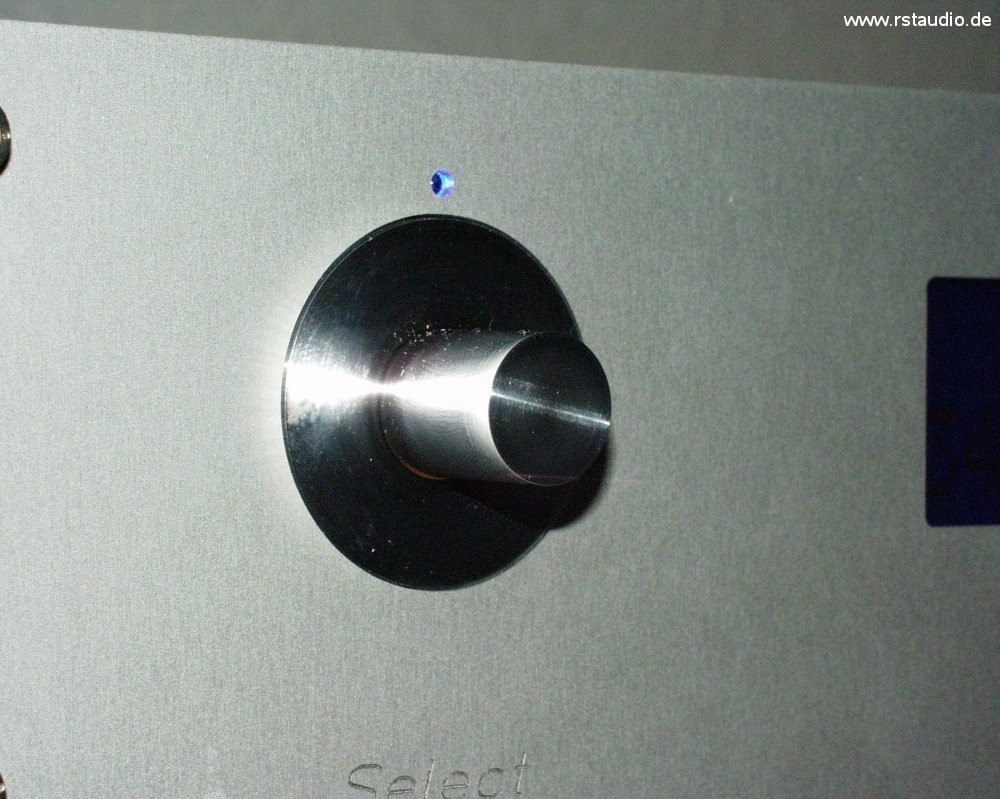
DIY Rotary Knob
At the end I have to named Rudolf B. and (once again) Enrico V. who gave me many tips and help to produce these nice cases. Without them I’am never able to finish this project in such a way.
!!! Many, Many Thanks !!!
The joy to look at the finished preamplifier is from time to time bigger than the joy for the music I play with it.
Wiring
2006/03/04
Here you find 3 schematics for the description of the wiring. The first describe the 230Vac system inside the Control Unit. The two others are for the signal wiring inside the Control Unit and the Audio Unit.
Final Control Unit
The 230Vac system is not only a pure point-to-point wiring. You find also a circuit to connect the analog ground to earth and a DC filter. Both circuits uses bridge rectifiers.
With the AC line filter J1 and the fuses F1 and F2 the AC gets into the Control Unit and is than switch with S1. The DC filter (BR1, C1, C2 und C3) eliminates the AC current from a DC offset and relieves the audio transformers. You find a good description for the calculations of the values on saque.de – sorry, it’s written in German language. With the diodes of the bridge rectifier the maximum voltage across the capacitors is 1.2V and therefore we have no problems with the wrong polarity of one capacitors at a time (as long as the voltage of the capacitors is above 25V).
Each ground is connected with two anti parallel diodes to earth (second bridge rectifier BR2). With this circuit the potential of the grounds are on the same level as the potential of the earth without a current flow.
The LED DS3 is connected between N and earth and shows opticaly wether the N connection of the preamplifier is wired to the external L1 or N. The user can see it immediately that he has a correct connection. You find this LED on the backside of the Control Unit. The LED’s DS1 and DS2 shows the availability of the power supplies for the μC and the relay power supply boards. XLR1 and XLR2 is used to connect the analog power supplies to the preamplifier boards in the Audio Unit.
PF1 on the μC board is the connector for the display and LK4 the input of the infrared receiver IC1 (TSOP17xx). The connectors LK5 and LK6 are used for the rotary encoders. A and B are the encoder signals and C the common point for both (here GND), D and E are used for the rotary encoder switch. PF2 is the I²C bus output which is connected with PF1 on the relay driver board. PF2 on this board is connected with the Sub-D 9 connector at the backside of the case. PF3 and PF4 are the relay signals and are connected with the two Sub-D 37 on the back.
Audio Unit Wiring
For the internal audio signal wiring I use a two pole shielded cable (also for the single ended cinch connectors). I solder the cables directly to the connectors and the PCB’s – this is not very flexible, but in my opinion the way to get the best connection.
From the 37 signals of the two Sub-D connectors (J1 and J2) only 36 where needed. You have to make two cables out of the 36 pole ribbon cable – a 26 pole cable for the volume / gain and a 10 pole for the input selector. The two LED’s DS1L and DS1R are glued at the front of the audio unit.
- Wiring of the Audio Unit
Connections between both Units
The photo above shows the cabling between both modules. On the rigth side we see the earth connection, then the ribbon cables to connect the relay drivers with the relays and the DC supply for both preamplifier boards via 4 pole XLR.
Updates & Improvements
2006/02/23
There is nothing what you can’t improve!!! Specially after you have finished a development you should know a lot more about your design and normaly you have new and maybe better ideas to improve the system.
[2005/09/07] Volume & Gain
The gain (the “inner” amplification factor) of the Aleph P is set with the resistor RG between R51 and R66. If you lower the value of RG you get a higher amplification factor. I soldered a fixed 2kΩ resistor on the preamplifier board and changed the 2kΩ resistor on the Volume / Gain board with a 124Ω resistor. With this I get the lowest amplification with no resistor switched on and the highest when all resistors are active. A nice thing I also get is that there is no “plopp” noise which I had when I changed the gain with the old implementation (because now I have a permanent connection of both halfs of the preamplifier).
[2005/09/23] Volume & Gain
A for me not satiesfied ended discussion about the pro and cons of non magnetic resistors in audio circuits had made me curious. So I ordered Dale CMF-55-143 resistors (68,1Ω, 113Ω, 249Ω, 499Ω, 1kΩ, 2kΩ, 4,02kΩ, 8,25kΩ, 16,2kΩ and 32,4kΩ) and soldered them on the Volume / Gain board. The judgement of the results is at least not possible because I have only one preamplifier and therefore I’m not able to make a direct A/B comparison between both versions. I imagine that there is a little improvement in the details, but at least I’m not sure if this is the truth – but I’m happy with my changes.
Volume and Gain with Dale Resistors
The blue normal metal film resistor at the right side of the connector is the current limiter for the LED and therefore has nothing to do with the audio signal – this is the reason why you not find a Dale resistor here.
[2005/12/23] Preamplifier
One of the biggest thing in the quality of this preamplifier is the quality of the coupling capacitors. I tried to get more out of the system with soldering 10nF styroflex capacitors (Reichelt Elektronik, Ordering No. STYROFLEX 10N) in parallel with the Wima’s. Once again, because I can’t make a direct comparison between both I’m not able to select the right ones. But I think the styroflex do nothing bad and therefore I leave them at their places.
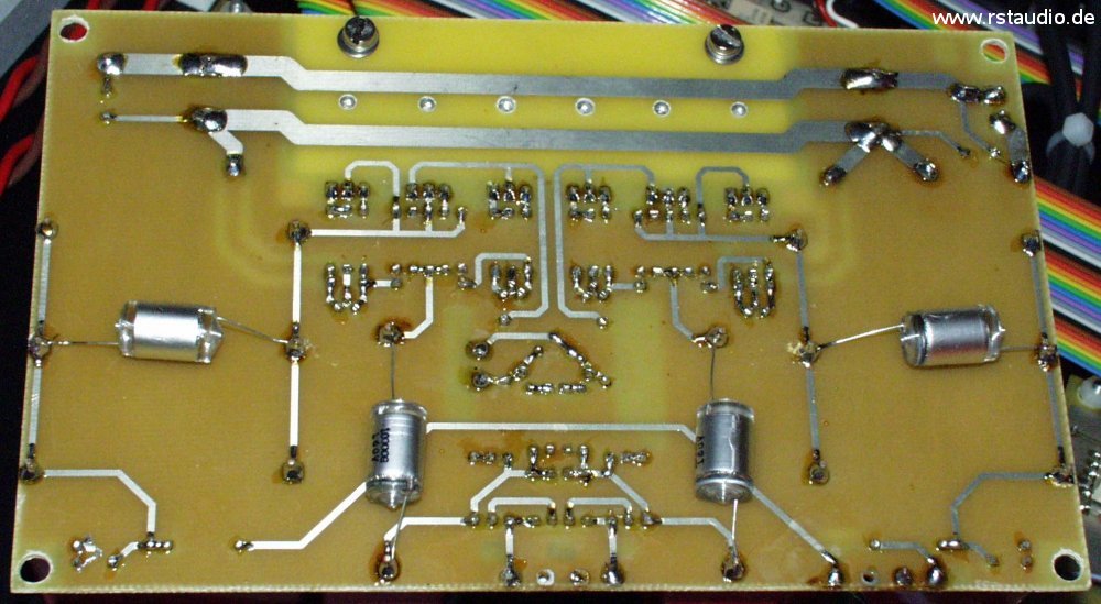
Preamplifier with Styroflex Capacitors
[2006/01/22] Preamplifier
Since I changed the resistors on the volume boards I have also Dale resistors for the preamplifier. In the meantime I also changed some smaller things at the PCB layout (round wires, the possibility to solder electrolytic capacitors at the input and output). With the new boards I leave the styroflex capacitors out (see above) – at least I can’t hear any differences.
With all resistors in the audio units coming from Dale the discussion of pro and cons is finished for me. The sound quality is much better and in the future I want to use such resistors all the time in my finished designs.
Preamplifier with Dale Resistors
Clones of my Aleph P
2006/08/11
At this place I want to show clones of my Aleph P Preamplifier.
[2005/12/06] Uwe K.
The difference between my preamp board and Uwe’s implementation is the bigger heat sink he use and the different position for the MOSFET’s. The layout of the board has also some minor changes to my first version.
Aleph P Clone from Uwe K.
Uwe wants to send more an better pictures …
[2006/07/25] Dragan P.
Dragan had worked out a very nice PCB for the controller board with the I²C relay driver integrated from my schematics. The display is also integrated at the back of the board.
Controller Clone from Dragan P.
Controller Clone from Dragan P.
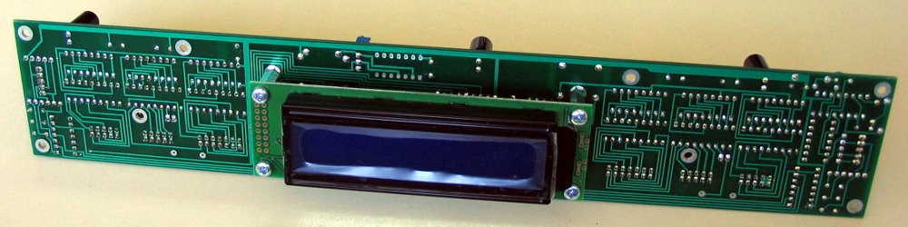
Controller Clone from Dragan P.
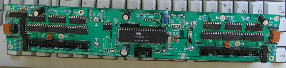
Controller Clone from Dragan P.
[2008/03/16] Peter D.
Peter’s Aleph P don’t use any digital control. The input selection and the volume setting is done via manuel switches. Peter used Mundorf MCap coupling capacitors instead of the Wima’s I have in use. What you can see is that there is more or less enough space on the PCB for this kind of capacitors.
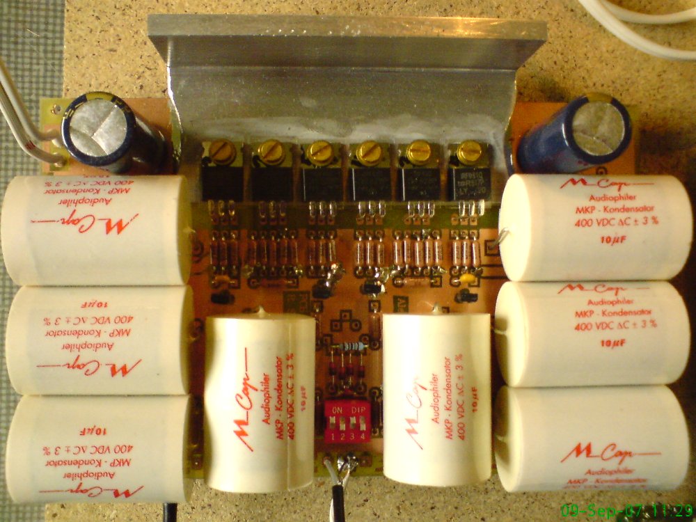
Aleph P preamplifier board from Peter D.
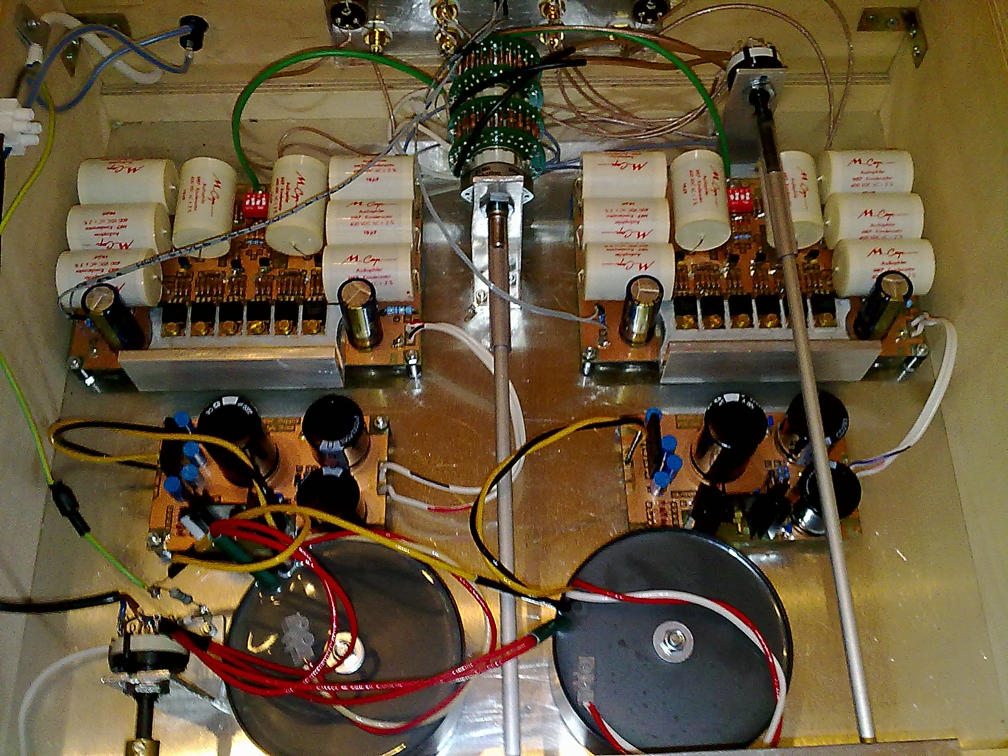
View of the complete electronic of the Aleph P
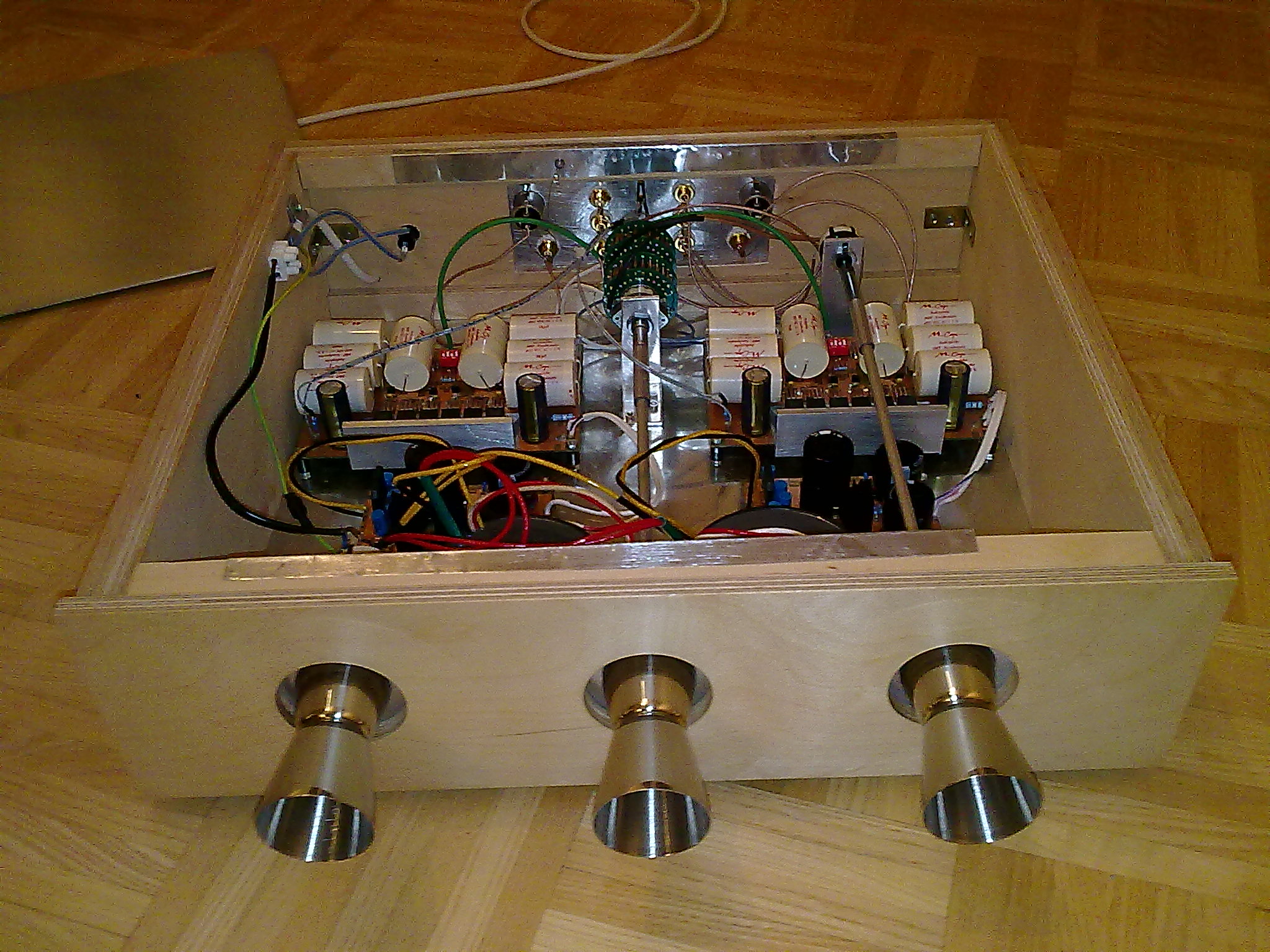
View of the front with an open Case