Table of Contents
Introduction
May 30, 2024
In the fall of 2023, my friend Uli asked me to build low-power power amplifiers for the midrange and tweeter horns of his four-way horn system. I didn’t have a suitable power amplifier on hand, but as I thought about possible circuit topologies, the Aleph J kept coming to mind.
I felt that the single-ended Class A design with the Aleph Current Source was ideally suited for this task. However, I wanted the power amplifier to be balanced. That’s how the Aleph JX came to be.
In addition, I didn’t want to use any of the p-channel Toshiba JFETs in the input stage, as they’re rather hard to come by these days. Instead, I reversed the polarity of the input stage and used n-channel JFETs. Of course, I then also had to change the polarity of the output stages to p-channel MOSFETs. This led to the name Aleph JXnp.
The output power was intended to be relatively low. I achieved this by reducing the operating voltage and halving the number of output stages. This is how the power amplifier got its final name: Aleph JXnp S.
- Aleph J: Circuit Topology
- X: super-symmetric Configuration
- np: Polarities of the FETs at the input and output
- S: Reduced Output Power (Small)
Description of the Circuit Design
March 18, 2025
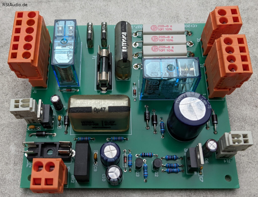
Audio Board
The output stage is driven by a differential amplifier using 2SK2145BL n-channel dual JFETs. These are still in production and are therefore easy to obtain. They can be found in all of my projects from recent years. By reducing the operating voltage to ±16V, they operate in the sweet spot. No additional cascode transistors are necessary. Compared to the design of the Aleph J, I use a precise reference voltage in the differential amplifier’s current source instead of a simple Zener diode.
Because the required output power is low, I’m using only a single output stage. However, due to the super-symmetrical design, two stages are actually needed. In this design, though, there are no two output stages connected in parallel. Naturally, I had to adjust the operating points to account for the lower operating voltage.
To stabilize the operating voltage of the output stage, I use two capacitive multipliers with adjustable reference voltages. This allows me to set the voltage to a specific value and keep it stable regardless of the current mains voltage.
I designed the power amplifier to deliver an output power of 10W into an 8Ω load.
Power Supply
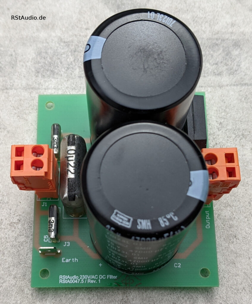
The unregulated power supply begins with a power jack featuring built-in fuses. The mains voltage is then filtered through a 230V/AC DC filter to remove any DC components that may be present. This prevents the transformer from being driven into saturation.
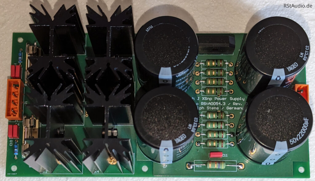
I specifically specified the toroidal transformer for this amplifier, and it was manufactured by Müller Elektrotechnik GmbH to their usual high standards. I decided to use one transformer for the power amplifiers. However, each channel has its own secondary windings. From the transformer onward, the power supply is designed in a dual-mono configuration.
The rest of the unregulated power supply for one channel is mounted on a printed circuit board. Following the connection of the two secondary windings are snubber networks. Next, the bridge rectifier is arranged with ultra-fast soft-recovery diodes in TO-220 packages. Each diode is screwed onto a heat sink. The rectifier is followed by CRC filtering with four 22,000μF capacitors and 0.2Ω resistors. Due to the constant current draw of the single-ended Class-A power amplifier, there is no modulation of the music across the resistors. Thus, this filtering technique can be used to filter out residual ripple from the DC voltage.
Inrush Current Limitation
The power consumption of this power amplifier isn’t particularly high. Nevertheless, I decided to limit the inrush current of the toroidal transformer. After all, the board in question also houses the circuits for remote on/off control. In a multi-channel system, it’s very helpful not to have to turn on all the power amplifiers manually.
Installation in an Enclosure
May 30, 2024
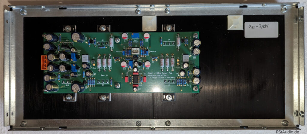
Of course, I used a chassis from Italy. This time, I decided on a model with 4U height and a depth of 400mm. Although the heat sinks can handle the heat generated by the power amplifier, they still get quite warm. But that’s normal for a single-ended Class A power amplifier.
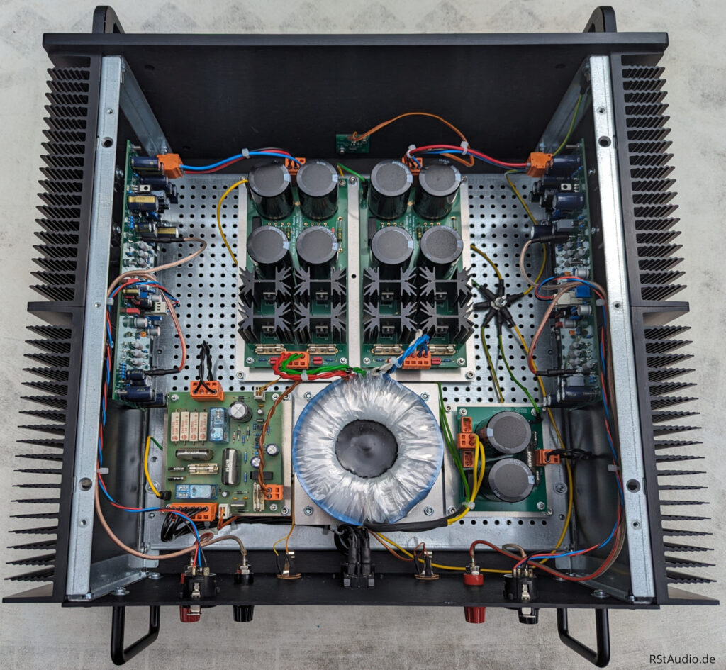
The photo above shows the interior of the power amplifier. I used a mounting plate with a perforated grid provided by the enclosure manufacturer. The two power amplifiers can be seen on the left and right, bolted directly to the heat sinks. The toroidal transformer is located at the bottom center. The transformer’s mounting plate is secured to the main mounting plate with rubber pads. To the left of it is the inrush current limiter, and to the right is the 230V/AC DC filter. Above the transformer are the two unregulated power supplies. To the right of them is the central grounding point.
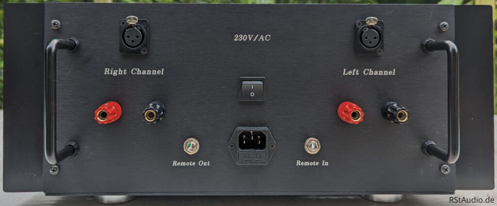
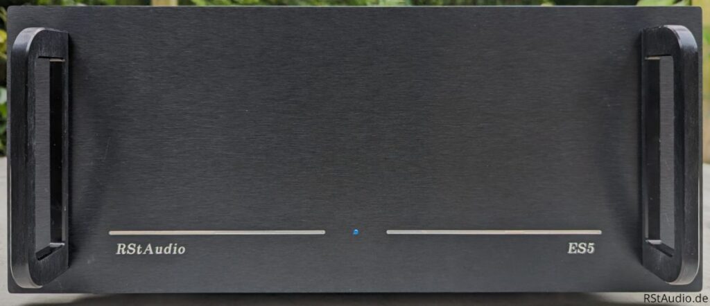
The rear panel of the ES5, shown in the photo above, is configured as one would expect for a power amplifier. In the center is the 230V/AC power input. To the left and right of it are the audio inputs and outputs. There are also two jacks for remote control.
The front panel (see above) is available in black upon request. The only control element on it is an LED that indicates the operating status.
Handles are attached to the front and back for easier handling. The handles on the back also protect the jacks.
Audiophile Review
In addition to the RStAudio XOno phono preamplifier and the RStAudio VV8 8-channel preamplifier, two RStAudio ES5 units have now been put into service here.
At my request, Ralph designed and built these specifically for horn-loaded speakers with relatively low power requirements, based on a Pass Aleph J circuit.
Ralph’s description clearly shows just how meticulously and carefully the power amplifiers were designed and built.
Because of the intentionally low power output, Ralph was only able to test these power amplifiers to a limited extent in his own system. As a result, there was a great deal of anticipation about how the ES5 would perform in the environment for which they were designed.
The commissioning took place on the memorable date of June 25, 2025.
After a good week of intensive testing, I can say that the “break-in period” isn’t just an empty phrase, but — albeit subjectively — does indeed lead to greater stability.
I find it difficult to describe sound, but I can tell pretty quickly when something bothers me. Nothing bothers me here. The high- and midrange drivers powered by these amplifiers produce a very, very clean and breathtaking sound.
In addition to my pair of ES5s, there’s another pair being worked on with Sato horns. I haven’t heard them yet, but from what I’ve been told, other highly regarded power amplifiers had to make way for the ES5s right away. I’m writing this because I don’t have anything to compare them to on my speakers. To be honest, I don’t want to compare them, because I’m happy and can’t imagine any better power amplifiers for my specific setup.
As a preliminary conclusion after a good week, I’d like to say that I can’t imagine any more suitable — and therefore better — power amplifiers!
Thank you, dear Ralph, for creating this wonderful piece of electronics, which has given my sweetheart and me the pleasure of listening to music like never before.
Uli J., August 3, 2025