Table of Contents
- Introduction
- Concept of the Preamplifier
- Signal Switching
- Installation in the Enclosures
- Audiophile Review
Introduction
September 27, 2022
The XC-22A line preamplifier in the VV5.2 and VV7 really impressed us. For me, it’s the best preamplifier I’ve ever heard in my system.
My friend Guido asked me to build him a stereo preamplifier based on the XC-22A line-level boards. In the summer of 2022, I finally decided to put together such a preamplifier for him. To do so, I used existing components. For example, the unregulated power supply comes from the XOno 2019 project and can also be found in my current VV7 preamplifier. The controller board is a modification of the one from the VV7 project. What was not available was a circuit board for signal switching — the only board I had to develop from scratch for the VV5.4.
When choosing a name, I deliberately decided to continue the numbering sequence of the VV5.2 preamplifier, since this project does not involve new audio electronics.
Concept of the Preamplifier
September 27, 2022
I built the preamplifier in two enclosures. The first enclosure houses the unregulated power supply and the controller, while the second contains the two audio boards and the signal switching circuitry. Due to the size of the audio boards and the fact that I needed some space in the enclosure for the signal switching circuitry, I had to move the controller board to the second enclosure. The connection from the controller to the audio electronics is made via a standard 25-pin Sub-D cable. Power is supplied as usual using Hirschmann industrial connectors and a custom-made cable.
I haven’t made any changes to the XC-22A circuit board and have incorporated it into this project exactly as shown in the VV5.2. The exact same circuit can also be found four times in my VV7 preamplifier, with two instances on each line-stage board. As I’ve mentioned several times before, I’m quite convinced of the audiophile performance of this stage.
Signal Switching
September 27, 2022
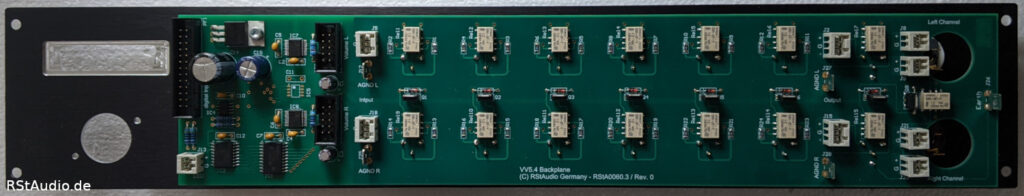
Since I’ve housed both audio boards in a single chassis, the signal switching had to be designed for two channels. However, to ensure there were still enough inputs available, I decided not to include any unbalanced RCA inputs on the board. There are six balanced inputs; if necessary, an unbalanced source must be connected to them via an external adapter.
The controller’s control signals are completely isolated from the audio signals. This applies first and foremost, of course, to the relays, which already ensure this isolation due to their inherent function, but also to the control signals sent to the two MUSES72320 volume chips. These are fed to the audio circuitry via an ADuM3154, which provides isolation for each channel.
To ensure that all signals, including proper shielding, reached the board, I decided to use a 4-layer PCB. I also used SMD relays to switch the signals. This prevents the signals from being routed unnecessarily through all layers of the board and allows the shielding of the ground layer to be particularly effective.
Installation in the Enclosures
November 28, 2022
As has been the case in recent years, HiFi2000’s slim-line enclosures with 10mm aluminum fronts are being used. As mentioned earlier, two enclosures are required to house all of the preamplifier’s electronics.
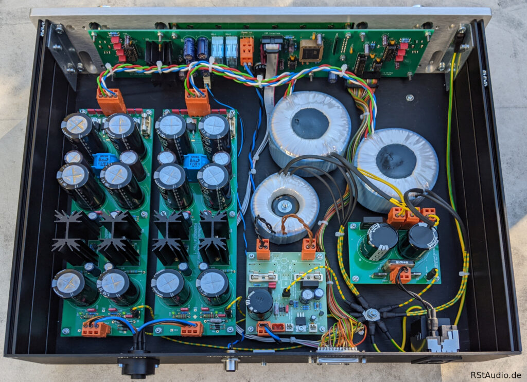
The photo above shows the interior of the power supply and controller enclosure. On the left side, you can see the two circuit boards for the analog, unregulated voltages of the audio circuit. To the right of that is the power supply for the digital electronics from the VV7. However, I did not need the controller’s remote-on function, as found on the VV7, which is why the board is only partially populated. The 230V/AC DC filter can also be seen on the right side.
I use three transformers for the operating voltages. This results in a dual-mono configuration for the audio circuitry. In addition, the digital circuitry is completely decoupled.
The controller board is located behind the front panel. As is my usual practice, the display, the two rotary encoders, and the IR receiver are connected directly to this circuit board; there are no cable connections.
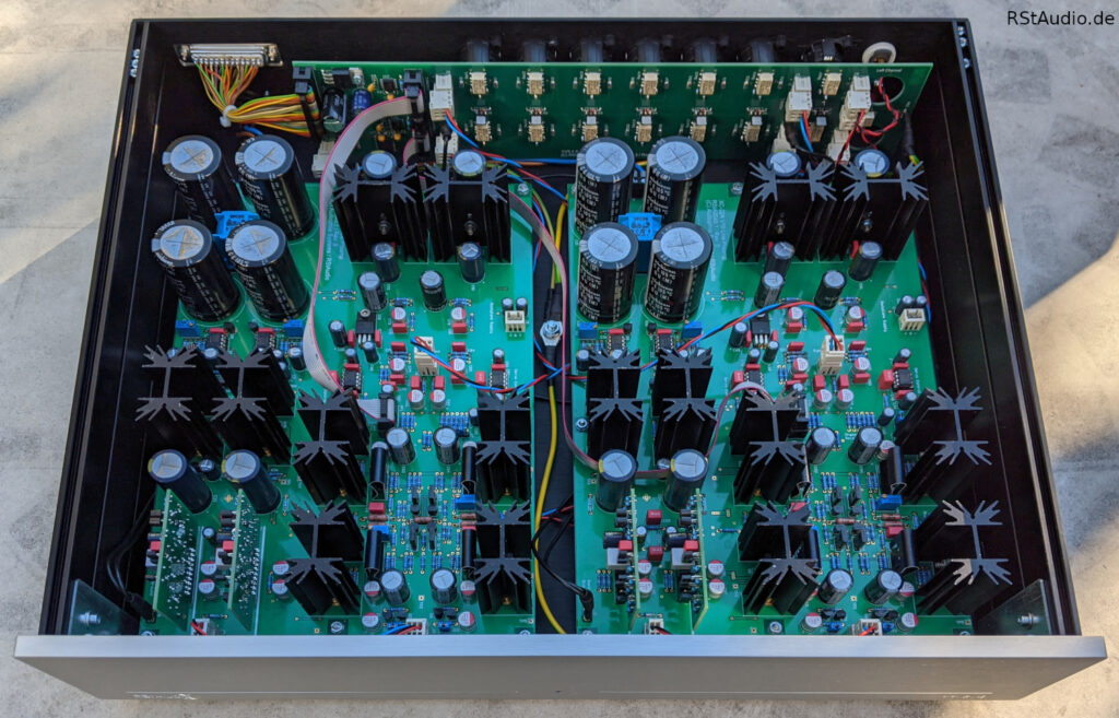
Looking at the audio chassis makes it clear what I described above. The chassis is quite full with the three boards. It was actually a bit of a challenge to route the necessary wiring in a reasonably neat manner. The layout is clearly visible: the two audio boards are screwed onto the bottom panel. The signal switch is mounted directly on the rear panel.
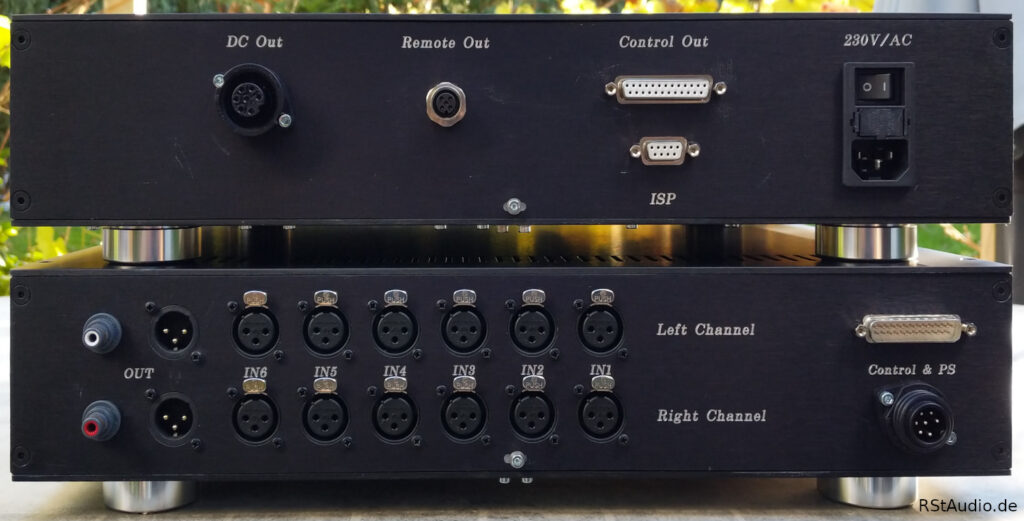
Last but not least, the backs of the two cases can be seen above.
On the right side of the controller’s rear panel is the Schurter power connector with a switch, fuses, and a filter. To the left of this is the connection labeled “Control Out,” which runs from the controller to the digital electronics in the audio enclosure. This connection transmits not only the digital signals but also the corresponding operating voltage. The microcontroller can be programmed via the 9-pin Sub-D connector labeled “ISP.” The “Remote Out” connection can be used to power on other components of a system, provided they are designed for this purpose. Finally, there is the connector labeled “DC Out,” which supplies operating voltage to the audio electronics.
On the rear panel of the audio enclosure labeled “Control & PS,” you can see the connection to the digital electronics and the jack for the analog power supply on the right. To the left of these are the six XLR inputs per channel. I always number them so that you don’t have to think twice when looking at the unit from the front. The outputs are located on the left side. There you’ll find the XLR outputs, which are directly connected to the outputs of the XC-22A preamplifier. Unbalanced output signals are provided at the two RCA jacks via two discrete operational amplifiers.
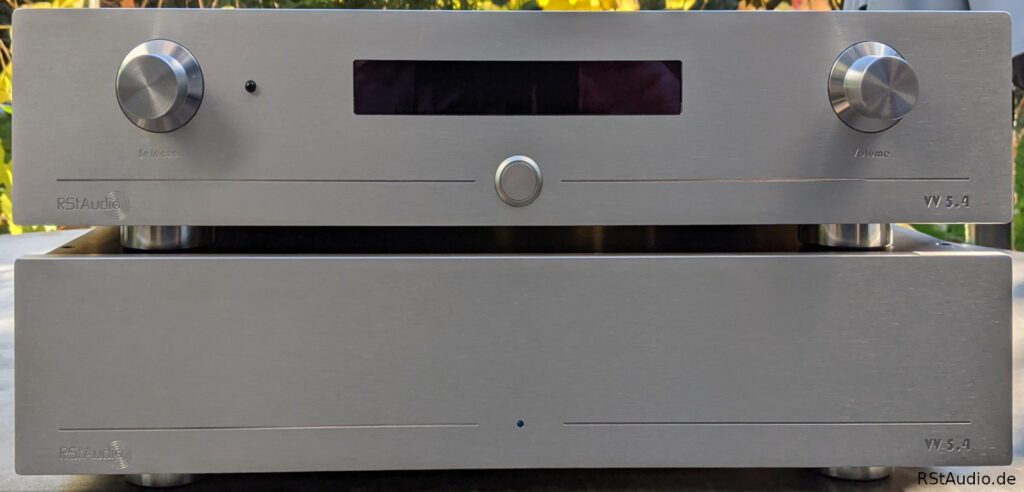
At the top of the page, you can see the front of the preamplifier. The design is the same as on all my devices from recent years. What makes this one special are the two front panels, which were once again manufactured for my friend Guido by a supplier for clearaudio. As requested, the lettering has not been blacked out. The display is located in the center of the controller housing. To the left and right of it are the two rotary encoders. To the right of the left rotary encoder is the IR receiver. The button below the display is used to turn the preamplifier on and off. Again, only the digital electronics are switched on or off; the audio electronics remain powered. On the audio housing, there is only one LED to indicate the operating voltage.
Audiophile Review
November 28, 2022
I don’t have anything new to report here that I haven’t already written about elsewhere on multiple occasions. For me, this preamp is the best one I’ve ever used in my system — and that includes both DIY builds and commercial models. I’ve tried quite a few of them, including some with a pretty good reputation. Even my beloved XP-30 replica has to admit defeat to this design.