Table of Contents
- Introduction
- Circuit Description
- Commissioning of the Prototypes
- Construction of the Power Amplifiers
- Reconstruction 2022
Introduction
June 10, 2010
I use four Quad ESL 57 speakers. They present a very challenging load, and it’s not easy to find a suitable power amplifier for these speakers. A key requirement for the right power amplifier is short-circuit protection. This becomes particularly difficult because I use two speakers per channel, which are connected in parallel. Power amplifiers based on a current-source design, such as the Zen or the Aleph, are of course ideally suited for this. I have been driving the speakers very successfully with the small Zens for some time now. However, these lack a bit of power, which is why I wanted to implement a similar design with more output power.
Having used the Zen power amplifier for many years, I naturally kept track of further developments on Nelson Pass’s DIY website. After closely following a discussion on the AAA forum about building an Aleph J and seeing the first positive results reported there, I decided in mid-2010 to build a pair of these power amplifiers in a mono configuration.
I would like to begin by noting that the design of this power amplifier is primarily based on the following patent by Nelson Pass, which describes the Aleph power supply.
- Amplifier Having an Active Current Source
Nelson S. Pass
US 5710522, Jan. 20, 1998
Circuit Description
July 1, 2010
The Aleph J is based on the circuit design of the Aleph series. It, too, employs a two-stage design featuring a p-channel JFET differential amplifier with a current source at the input and a single-ended Class A output stage based on the Active Current Source concept with two output stages connected in parallel.
In the accompanying user manual, Nelson Pass describes the amplifier itself as follows:
…
Meanwhile, it’s been about 13 years since I designed the Aleph 3, and I have such affection for that series that I revisited the design.
…
The Aleph J has about 15dB less negative feedback than the original and achieves comparable distortion, bandwidth and damping figures. It also has about 15dB less noise. Those of you with delicate tube preamps will be happy to see a 242kΩ input impedance with vanishing capacitance.
I consider it the best of the Aleph series.
The Aleph J carries on in the tradition of the Pass Labs Aleph series, combining those elements that were particularly right about the Aleph 3 and 30, and re-thinking those areas open to improvement. Unlike its First Watt predecessors the F1 and F2, the Aleph J is a voltage source amplifier – a regular sort of amplifier like the ones you already know and love.
There are differences between the Aleph J and its predecessors:
- Improved power supply filtration with about 20dB less voltage ripple
- Reduced gain on the active current source, giving better overall performance into 8-16 ohm loads
- Input stage using high quality matched JFETs
- Much higher input impedance and vanishing capacitance
- 15dB less negative feedback
- Even greater stability, operating without lag compensation
- 15dB less noise
- No electrolytic capacitor in the signal path
Some things have remained the same – the Aleph J has the same basic 2-stage topology and uses output MOSFETs operating in single-ended Class A mode. It’s distortion is still 2nd harmonic, and it’s sound is still natural and liquid. It is still very reliable. I don’t know of a load that can
damage it.…
The published technical specifications for the amplifier are as follows:
| measured at 120V AC with an 8Ω load | |
| Input Impedance | 242kΩ (RCA input) |
| Damping Factor | 20 |
| Output Power | 25W with 1% THD at 1kHz 30W clipping |
| Gain | 19.6dB |
| Input for 25W output | 1.5V |
| Maximum output voltage | ±21V |
| Maximum output current | ±2.5A |
| Noise | 100µV unweighted, 20Hz-20kHz |
I’ve made a few minor changes to the original design. Now, both the current source for the input differential amplifier and the values of the two current sources at the output are adjustable. Both of these allow me to adjust the operating point of the power amplifier. The current setting at the input differential amplifier is particularly important, as its value directly affects the offset voltage at the speaker output.
For the source power resistors and the resistors at the output, I used two 1Ω/2W resistors connected in parallel in each case. As the coupling capacitor in the negative input, I used the same 10µF Panasonic film capacitors as in my X0 replica. The coupling capacitor in the feedback loop of the Aleph Current Source consists of a 220µF Panasonic FC electrolytic capacitor and a 47nF Panasonic film capacitor (same type as above) connected in parallel.
Since Nelson Pass has not published the circuit for this amplifier, I will refrain from doing so as well. However, those interested will surely find it on the AAA forum or on DIYAudio. Alternatively, you can also contact me by email.
Commissioning of the Prototypes
July 1, 2010
I built the first Aleph J power amplifier on a heat sink from HiFi 2000 (300 mm × 210 mm × 40 mm). The heat sink has a specified thermal conductivity of 0.2 K/W, but measured values are closer to 0.3 K/W. The operating voltage is supplied by two adjustable power supplies from the automation industry. During installation, I set both trimming resistors (see above) to the values of the corresponding resistors in the original circuit.
I didn’t have to make any changes to the trimmer for the output current sources. The current was almost exactly 1.15 A per current source at a voltage of approximately 570 mV across the source resistors. The deviation between the individual MOSFETs was less than 10 mV, which indicates that the transistors are very well matched. I purchased them on eBay. By the way, I simply soldered the source resistors into the circuit straight from the bag without testing them.
I had to adjust the current from the input differential amplifier’s power supply. Once the power amplifier had reached its operating temperature, I was able to set the offset to approximately 0.7mV. However, a more thorough investigation of the offset voltage at the speaker output is still pending. That said, this value has so far been restored every time the circuit has been turned on after warming up.
Based on the Aleph J alone, I can say that replacing the Zen power amplifiers will significantly improve my system. The differences are truly striking, which is why I’m eagerly awaiting the remaining components so I can finally put the two power amplifiers into operation.
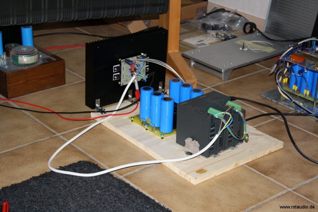
In the meantime, both power amplifiers are operating as prototypes. The power supplies also largely correspond to the final design of unregulated power supplies with CRC filtering (4× 47,000µF and 2× 0.2Ω). The toroidal transformers are custom-made in the usual high quality from RONDO Toroidal Transformers by Müller Elektrotechnik GmbH.
As described above, I left the trimmers on the output current sources set to the value of the original resistor. However, after measuring the effect on a power amplifier, I concluded that an adjustable resistor at this point is completely unnecessary. Consequently, I replaced the trimmer with a fixed resistor on both power amplifiers.
As for the sound quality, I can only say that it far exceeded my expectations. The Aleph J is head and shoulders above the Zen and brings out details I’ve never heard before on my LPs and CDs.
The Aleph J is a huge step forward for my system!!!
Construction of the Power Amplifiers
October 8, 2010
My tests with the prototypes have shown that it’s worth powering each speaker in my Stacked Quads individually with an Aleph J. That means I need a total of four power amplifiers. I have therefore decided to build two stereo power amplifiers, one per channel.
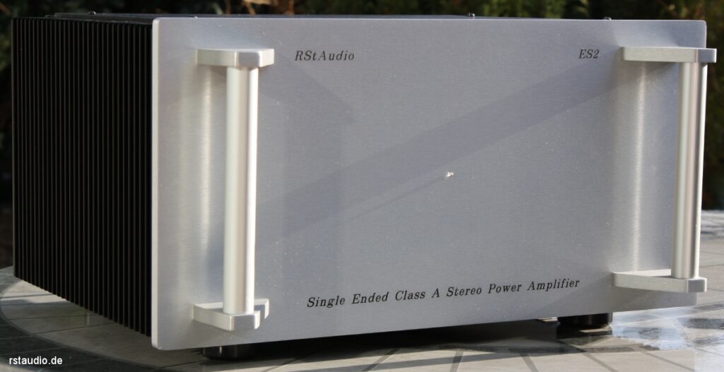
These power amplifiers are built around the Pesante Dissipante 5U chassis from HI-FI 2000, which features two of the heat sinks mentioned above (part number 1NPDA05300B). The chassis is made entirely of aluminum and features a 10-mm-thick silver front panel, a bottom panel without ventilation slots, and a top panel with ventilation slots.

Since the 2SJ109BL transistors were no longer sufficient for four output stage modules, I redesigned the circuit board and used two matched 2SJ74BL transistors in the input differential amplifier. In addition, the unnecessary adjustment of the output current sources has been eliminated (see above). I also widened the traces for the operating voltages and the output.
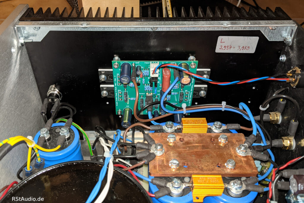
Each Aleph J module is mounted on a heat sink. This allows the four power MOSFETs to be soldered directly onto the circuit board, resulting in very short signal paths. A thermal switch monitors the temperature and cuts off the 230V AC power supply as soon as the temperature exceeds 75°C. I also mounted an aluminum bracket on both heat sinks to which the mounting plate for the power supply is attached.
To use one stereo power amplifier per channel, the input signal from one channel must be routed to both power amplifier modules. Since the input impedance of the Aleph J is very high (see above), there are no issues with this parallel configuration. However, I wanted to keep the stereo power amplifiers as flexible as possible so they could also be used in a 2-channel setup. For this reason, there is a switch on the rear panel that allows both inputs to be configured separately (stereo) or in parallel (dual mono).
I also connected a muting module to the outputs of both power amplifiers. This circuit short-circuits the outputs when the power is turned on or off to prevent unwanted noise. The muting module is based on a corresponding circuit section from the original XOno.
These power amplifiers are also turned on and off remotely from the preamplifier in my system, which requires a remote control circuit. In addition, the transformers, with their approx. 400VA, are just barely within the limit of tripping the house circuit breaker due to the inrush current. That is why I use the same remote circuit with inrush current limiting in the Aleph J as I do in my Hypex power amplifier.
Since my prototypes are completely silent (when there is no signal, of course), I decided not to regulate the operating voltage. For the two stereo power amplifiers, I use a single toroidal transformer for both channels (400VA / 4x 19.5V/5A). While this deviates from my general philosophy of a dual-mono configuration, it saves space inside the chassis. When using one stereo power amplifier per channel, I again employ my preferred method of separating the power supplies per channel. In the 230V/AC input line of the transformer, I use two 22,000µF/25V electrolytic capacitors and a bridge rectifier as a DC filter.
After the shared transformer, the operating voltage supplies for both channels of the power amplifier are designed using a proven dual-mono configuration. Each channel features two rectifiers and a CRC filter comprising four 47,000 µF/40 V electrolytic capacitors and two 0.22 Ω/25 W resistors. The two grounds (left and right channels) are each connected to ground via a bridge rectifier.

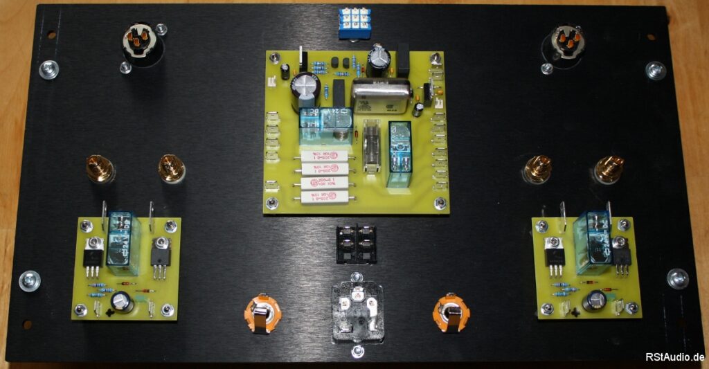
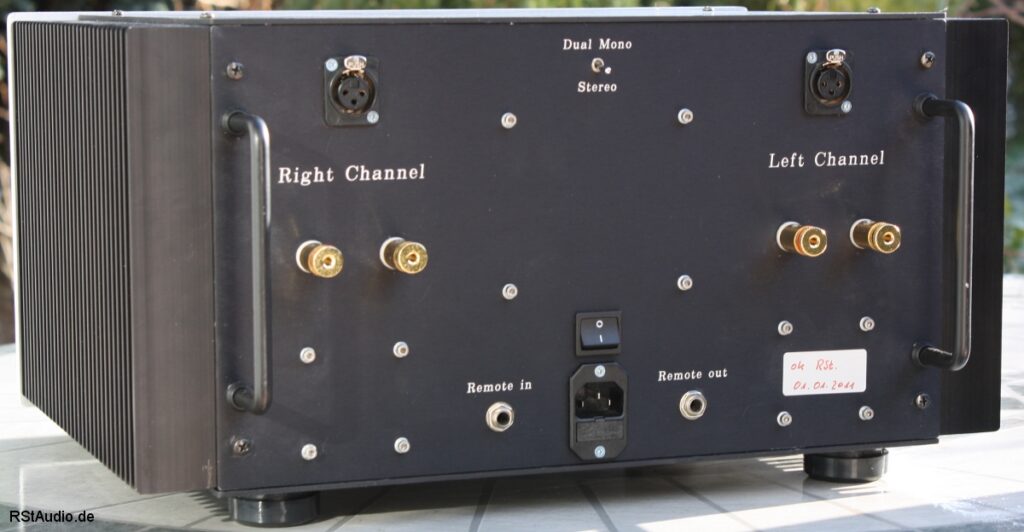
Finally, here is a picture of the back of the power amplifier. Visible are the two inputs (XLR jacks) as well as the speaker outputs, which are assigned to the respective channels on both sides of the rear panel. At the top center is the stereo/mono switch, below which are the power switch and the power socket with an integrated fuse. Next to these, on the left and right, are the input and output for the remote signal (6.3mm mono jack).
Reconstruction 2022
December 24, 2022
Since May 2022, I have been using one of my two Aleph J stereo power amplifiers for the high-frequency range of my RQM speaker system. Even though the XA30.8 is the superior power amplifier, the Aleph J performs exceptionally well when driving the Air Motion Transformers. Furthermore, I have never lost my fascination with the Aleph J’s single-ended Class A technology.
Unfortunately, both of my power amplifiers are now producing clearly audible noise. I’m certain this is due to a temperature-related issue. Unfortunately, my attempts to fix the problem have not been successful. That’s why I decided to redesign the audio circuit board in October 2022.
In doing so, I not only designed a new circuit board, but also made some changes to the circuitry — changes that I believe are very beneficial.
- To operate the JFETs in the “sweet spot,” I added cascode transistors to the input stage.
- The reference voltage for the input current source is no longer generated by a simple Zener diode.
- For the current source, I use a bipolar transistor in a TO-225 package (higher power dissipation).
- Switchable servo regulator for a regulated, DC-free output.
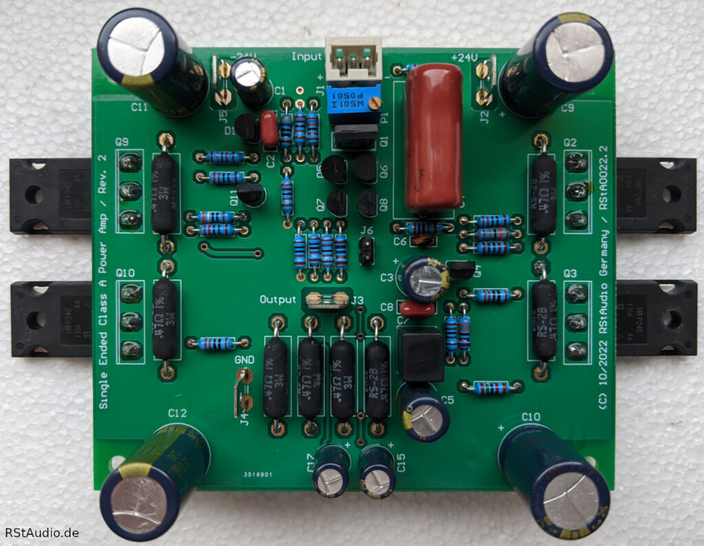
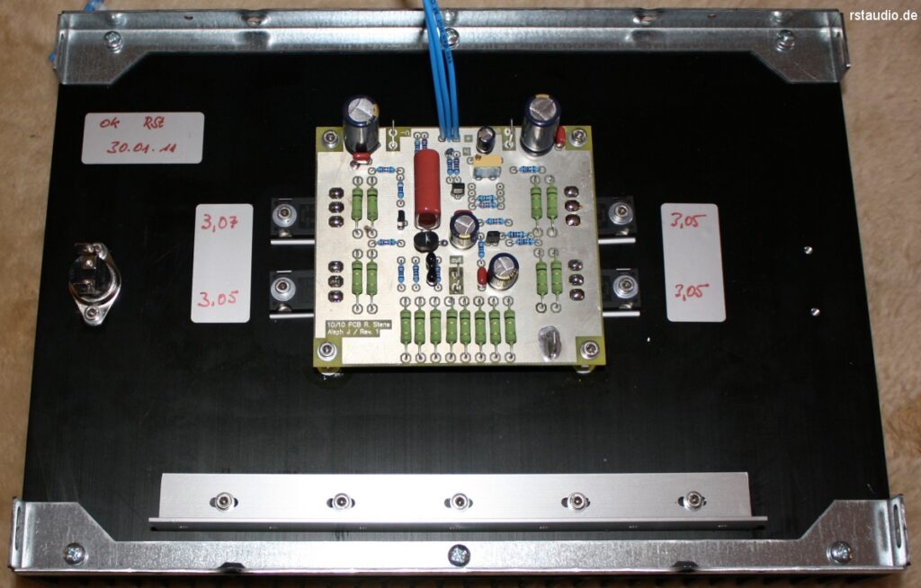
The photo above shows the assembled circuit board of my Aleph J R2. Upon closer inspection, you can see four transistors in TO-92 packages below the trimmer. Two of them are 2SJ74BLs, and the other two are BC560C bipolar transistors that function as cascode stages for the JFETs. These transistors allow me to operate the JFETs in their sweet spot.
The trimmer is used to adjust the current from the input current source, which ultimately also changes the output offset.
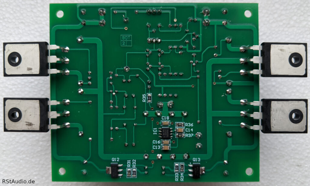
On the solder side of the circuit board, you can see the operational amplifier functioning as a servo regulator. The two transistors step down the amplifier’s operating voltage to the ±15V required by the op-amp. The servo regulator is activated via a jumper only after the offset at the output of the power amplifier has been optimally adjusted by manually balancing the input current source.
The Aleph J R2 has been running in my system since December 22, 2022.