Table of Contents
Introduction
28-01-2020
There is a phenomenon in conjunction with my Quads that I have observed for many years but have only understood in the last few weeks. The loudspeakers have a “day form”, they are sometimes quieter than usual and I have to drive more level to hear the same perceived volume. For a long time I considered it to be my personal daily condition, but the investigations of the last weeks showed that it is the loudspeakers themselves. The reason is the varying mains voltage (allowed: 230V/AC ±10%) which has a direct effect on the bias voltages of the foils. Different bias voltages cause changed deflections – and thus volume – of the Quads. To eliminate this effect I developed the RStAudio ESL AC Voltage Regenerator.
In addition, since the renovation of the loudspeakers I have problems with sparkovers in the tweeter unit when the mains voltage is above 230V/AC.
Investigations with Spice
28-01-2020
To confirm my suspicion I have once again Spice attempted. With this software it is very easy to determine how the actual conditions on the foils should be.
My 4 Quads are designed for 220V/AC and bring this voltage by transformer to 610V/AC. Then the voltage is multiplied by Greinacher cascades to a DC voltage of about 1500V/DC for the high frequency panel and to about 6000V/DC for the two bass panels. A first simulation with these parameters calculates the voltages at the loudspeaker modules as provided by the manufacturer.

This results in foil voltages of 1467V/DC in the high frequencies and 5835V/DC in the bass. These are the ideal values specified by the manufacturer. Of course there was also a tolerance band of the mains voltage at the time of the development of the Quads 57 and I think at that time it was ±10%. But I claim now that the mains fluctuations at that time – at least in country areas – were not as big as today.
Next I took a look at how it looks like with an ideal mains voltage of 230V/AC on the foils.
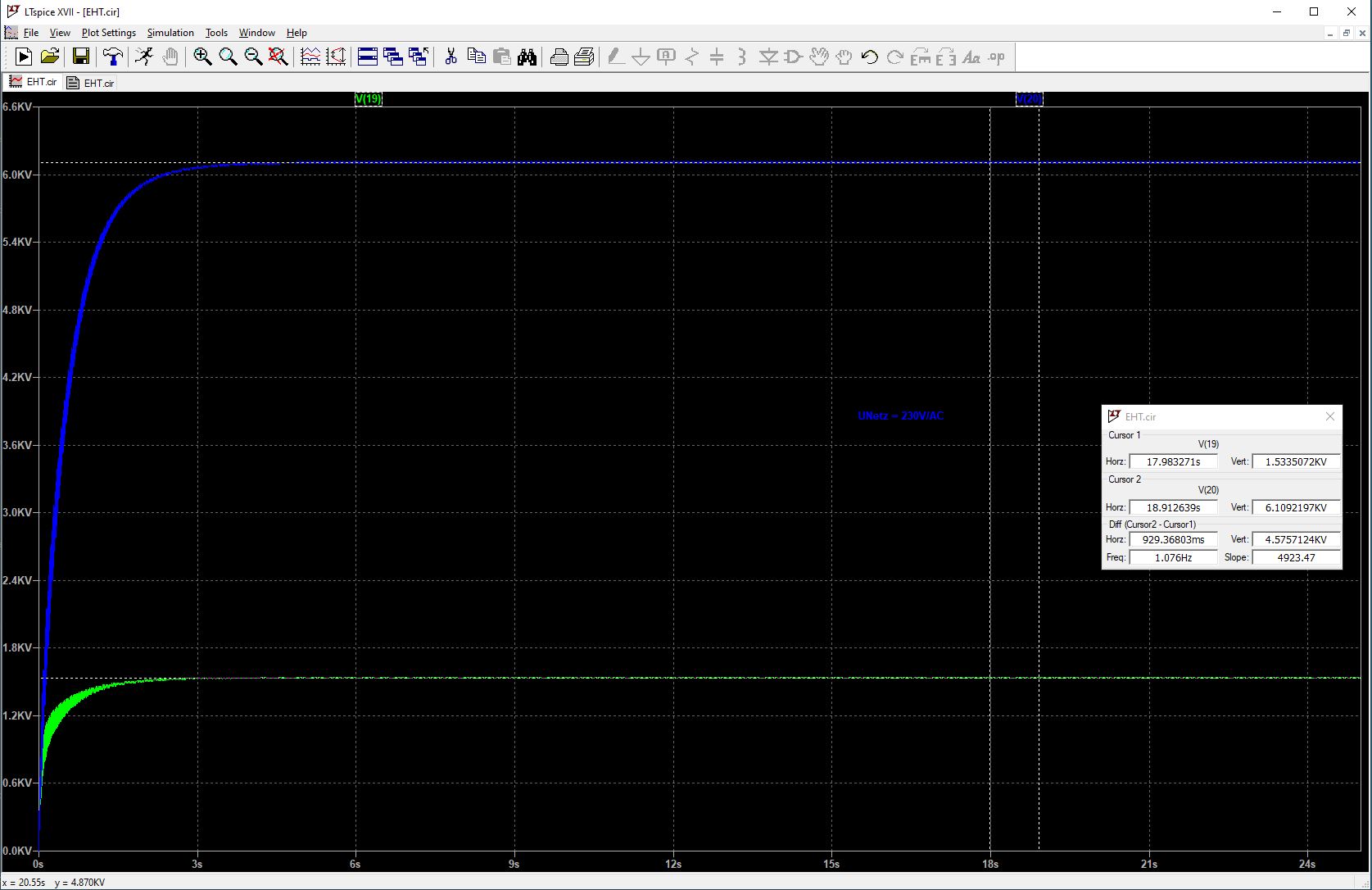
The simulation gives 1534V/DC and 6109V/DC. An increase of 67V/DC in the treble and 274V/DC in the bass. This is about 4.6% more voltage than intended and is still within the tolerance band of 220V/AC ±10%. The operation of my Quads at ideal 230V/AC will be quite permissible.
If we look at the voltages in the tolerance band of ±10% around 230V/AC, we get the following picture:
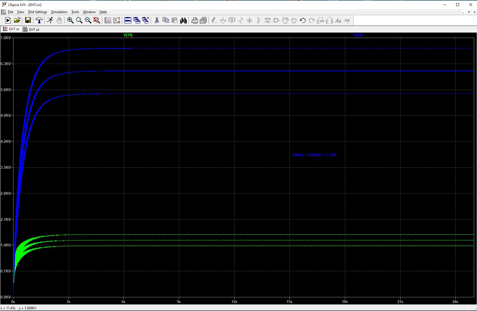
The two middle curves (blue & green) are the results at 230V/AC mains voltage and the two outer curves are the voltages at 207V/AC (-10%) and 253V/AC (+10%), i.e. at maximum utilization of the permitted tolerance band of the mains voltage. The following table shows a summary of the resulting voltages:
| Netzspannung Mains Voltage | 220V/AC | 230V/AC - 10% | 230V/AC | 230V/AC + 10% |
|---|---|---|---|---|
| Hochton High Frequency | 1467V/DC | 1380V/DC | 1534V/DC | 1687V/DC |
| Bass Low Frequency | 5835V/DC | 5491V/DC | 6109V/DC | 6715V/DC |
As can be seen from the simulations, the actual film voltages depend on the voltage currently applied from the grid side. In my case there are voltage fluctuations of more than 10V/AC in the last hour before I wrote these lines. Depending on whether the sun is shining or not, completely different basic values occur – around our house there are a lot of photovoltaic systems installed.
Now, however, the applied foil voltage has a direct effect on the resulting deflection at a defined input signal. The result is a basic volume of the Quads 57 that changes with the mains voltage. This is not surprising if you consider that the foil voltages are generated directly from the mains voltage without any regulation.
Since I don’t have models of bass and treble panels, the loads on the cascade are realized by resistors. Thus the current flow in my simulation is directly linearly dependent on the voltage – Ohm’s law applies. But I think you can live with this limitation and it does not reduce the results.
The EHT units of my revised quads are no longer connected to the secondary 610V/AC winding, but to 590V/AC. At least my 4 Quads provide this voltage additionally. So you get a much better adaptation to the intended operating points at 230V/AC than with the original wiring.
Voltage Regenerator
01-12-2020
So what can you do to get stable conditions on the Quads?
The simplest thing is to provide the Quad with a stable input voltage that is independent of the current mains voltage situation.
This can be achieved relatively easily with a 50Hz or 60Hz sine wave oscillator with a following power amplifier including an output transformer.
The frequency signal is generated by a DDS chip (AD9833). A 10MHz quartz oscillator is used as reference clock. The DDS chip has to be initialized after power on and so an additional microcontroller is needed. I decided to use a Silicon Labs EFM8 Busy Bee. This controller also initializes the digital potentiometer which is used to set the output voltage.
After the DDS chip, the sine signal is amplified, filtered and freed from its DC component by a servo controller. This conditioned signal is sent to the power amplifier via the digitally adjustable potentiometer. I decided to use two integrated audio amplifiers LM1875 which are connected to a bridge amplifier. The transformer winding is therefore between the outputs of the two amplifiers. The output power is designed for 2 Quads ESL 57.
The output voltage can be slightly adjusted via a DIP switch. I have set the output frequency to 60Hz. This means that the high-voltage cascades are charged 10 times more per second than with the 50Hz that we usually use.
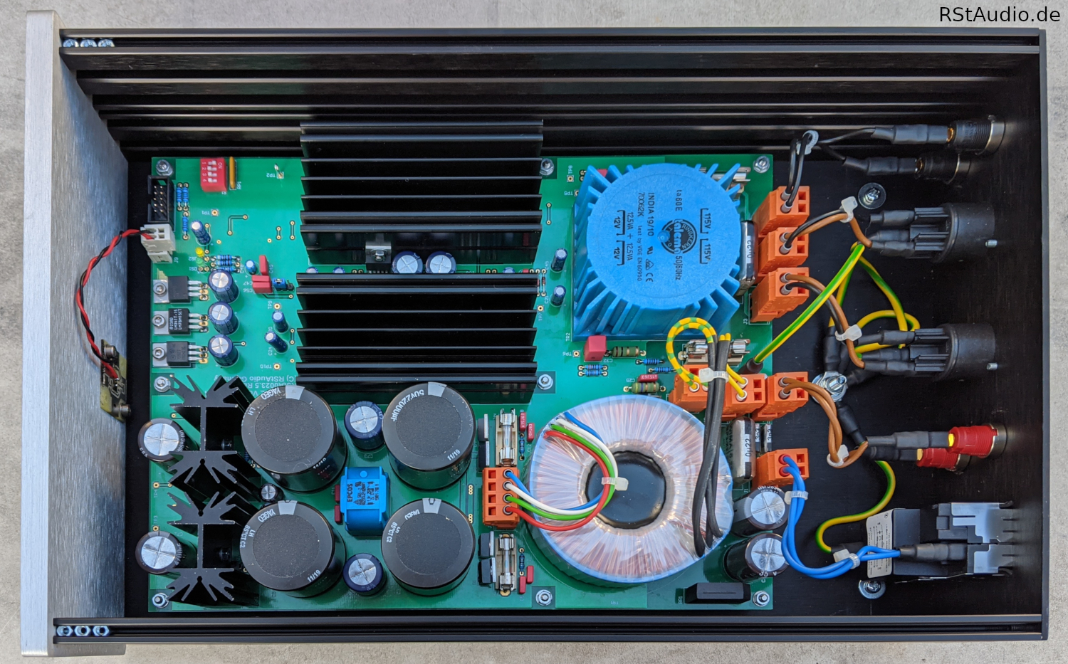
Of course the circuit needs an operating voltage. I have designed this in the usual complex circuit technique. After the mains filter there is an additional filter with MP2 X2 and Y2 capacitors. This is followed by a DC filter for the 230V/AC voltage. Only after these 3 filters the primary winding of the 45VA toroidal transformer is connected. On the secondary side there are snubber networks before the AC voltage is passed through a discrete rectifier with ultra-fast soft recovery diodes. This is followed by a symmetrical CLC filter. The unregulated operating voltage is then generated by capacity multipliers. These voltages supply the two audio amplifiers. Additionally there are ±15V and 3.3V voltage regulators for the supply of the operational amplifiers and the digital electronics.
For a large part of the signal processing I used SMD components. These are mounted on the bottom side of the PCB and therefore are not visible on the photo below.
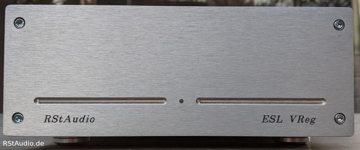
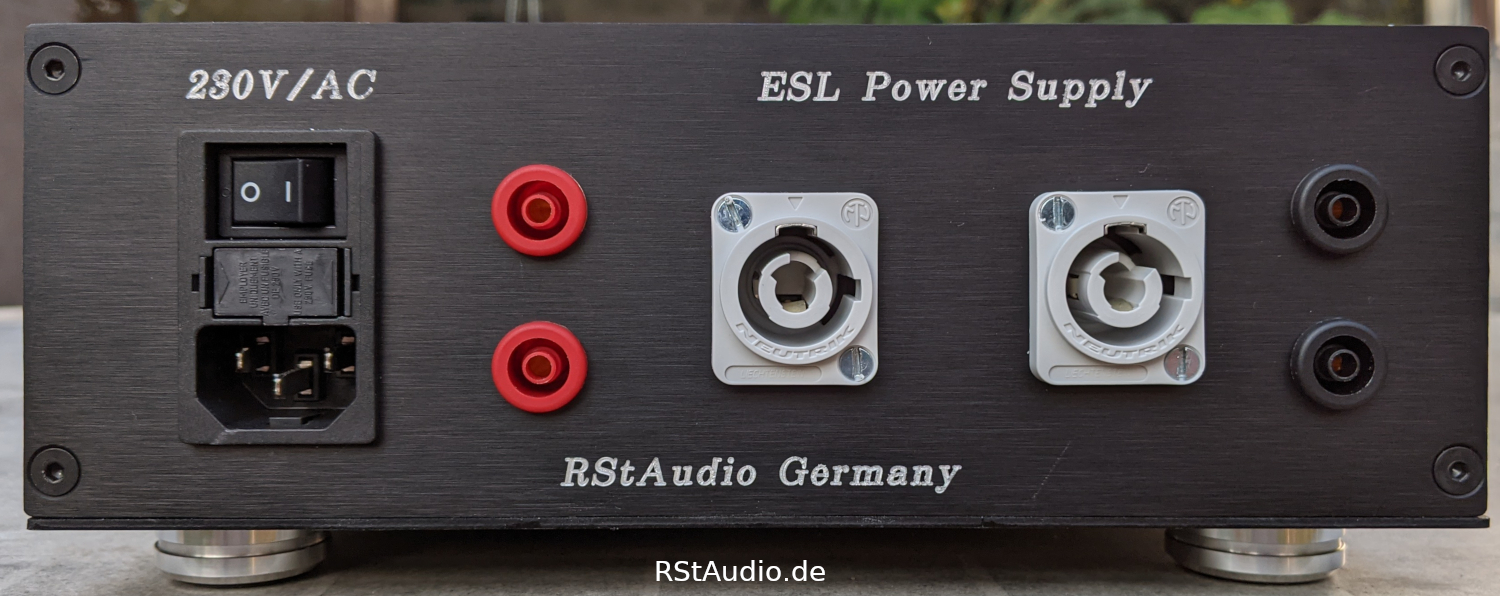
The front of the device is shown at the top of this page. There is only one light emitting diode which indicates the operating status. The back side can be seen on the photo below. On the left is the 230V/AC power input with mains filter, fuses and switch. At the red 4mm safety lab jacks the mains voltage can be tapped and measured after the DC filter. At the two following Neutrik Power Con sockets the Quads are connected. The black 4mm safety lab jacks are connected to the output of the device. Here you can measure the voltage on the Quads.
With the help of this circuit, the “daily form” of the Quads is gone. In addition there are no more sparkovers due to a too high mains voltage. I am very satisfied with this development and the resulting operating behaviour of the Quads.
But what is the voltage situation at my Quads? First of all the technical boundary conditions:
- The internal transformers of my Quads are re-soldered to a secondary voltage of 590V/AC.
- The output voltage of the Quad ESL AC Voltage Regenerator are set to 220V/AC.
- The output voltage has a frequency of 60Hz (see above).
This results in approximately 1450V/DC at the tweeters and 5680V/DC at the bass panels.