Table of Contents
Introduction
10-11-2019
In my two active crossovers there are circuit parts which allow a frequency-dependent signal influence in the subwoofer channel. But the analog circuitry offers only limited possibilities compared to the digital signal processing of a DSP (Digital Signal Processor). Since there was an active absorber – an miniDSP 2× 4 board left from another running project, I decided to use it for a subwoofer equalizer.
When used as an equalizer in the mono subwoofer channel, only one input and one output of the DSP board is required. The second input and the 3 additional outputs of the miniDSP therefore remain unconnected and are deactivated in the corresponding software.
The entire installation consists of the following components:
- miniDSP 2×4 Kit with Advanced Plug-In
- 1 symmetrical input
- 1 symmetrical output incl. a gain stage
- 1 power supply for the analogue circuits
- 1 power supply for the miniDSP and the Remote circuits
- Remote On/Off
Description of the Hardware
26-03-2018
Informations of the DSP board you can find here and details of the software plug-in you find here.
The entire audio circuit can be bypass with a relay. The input is connected directly to the output to route the signal passively through the SubDSP. The relay is activated by a switch on the front panel of the housing.
The balanced input signals are matched to the unbalanced input of the miniDSP board with an INA134 (Audio Differential Line Receiver). At the input of the line receiver there is a voltage divider which is used as input resistance and for level adjustment for the DSP board. The jumpers on the miniDSP board for input sensitivity must be set to 2VRMS.
The output signal of the miniDSP is routed via an AC coupling (C14) to a Butterworth low pass filter of 4th or 8th order (jumper J4) with a cut-off frequency of 250Hz and a gain of VU=2. The AC coupling is necessary because the output signal of the miniDSP – at least on my board – is not DC free. The low pass suppresses the resonance frequency of the RiPol, which is about 300Hz. The levels at the outputs of the DSP board are not very high – max. 0,9VRMS, therefore the filter has a gain greater than 1.
The analog power supply consists of a 10VA toroidal transformer followed by a Snubber network and a discrete bridge rectifier. This is followed by a classical design with 7815 and 7915 fixed voltage regulators. As a special feature I use voltage regulators from NJM.
In order to integrate the SubDSP into my system, I also needed the possibility to switch the device on and off remotely with a DC voltage. In addition, a DC voltage is required for the power supply of the miniDSP board. These voltages are supplied by the second power supply unit on the PCB.
The power supply for the DSP board is kept simpler than the analog power supply – no Snubber network and no discrete bridge rectifier. The ground of the DSP supply is connected to the ground of the analog power supply.
The circuitry for the remote control can be found in all my devices and offers me the possibility to switch the whole chain with the preamplifier on and off. All the devices involved are connected in series and each device ensures that the next one is switched on with a time delay. This ensures that e. g. two power amplifiers do not simultaneously load the domestic grid with their high inrush currents.
The circuit around IC7 is the input – Remote In. The DC input voltage of the previous device is regulated to 6V with the voltage regulator and the relay REL1 is switched. This switches the 230V/AC supply of the SubDSP. The relay is bridged by a mains switch, so the device can also be switched on and off with a conventional mains switch.
The second part of the circuit generates the time-delayed DC voltage for the following device – Remote Out. The unregulated DC voltage is switched to the output by means of Q1. Q1 is switched on by Q3 with a time delay. The time constant is defined by R15 and C42. Q2 is used as a current limiter to prevent Q1 from being destroyed in the event of incorrect operation.
- Circuit Diagram of the symmetrical In- and Output
- Circuit Diagram of the Low Pass Filter
- Circuit Diagram of the Power Supply
- Circuit Diagram of the analog Power Supply
- Circuit Diagram of the Remote On/Off
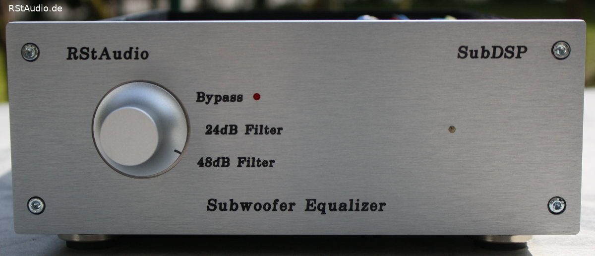
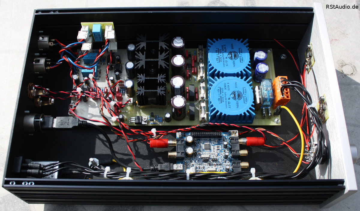
On the following picture you can see the complete electronics installed in the housing. As always, I use a HiFi-2000 cabinet. Above in the picture you can see my electronics, below you can see the miniDSP board. On the front panel there is a knob with which you can choose between Bypass, 24dB Filter and 48dB Filter. The bypass setting is also indicated by a red LED.
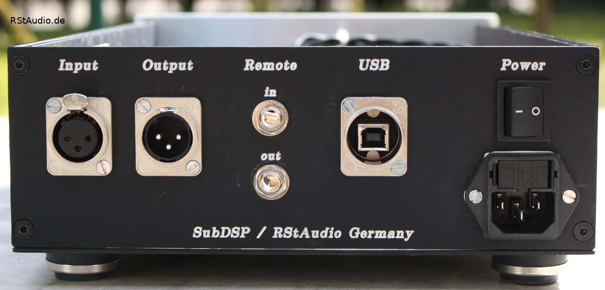
The next picture shows the rear panel of the SubDSP. On the left you see the two XLR connectors of the audio input and output, followed by the two 6.3mm mono jacks for remote control. This is followed by a USB socket, which is used to program the miniDSP. On the right you can see the 230V/AC supply. I do not normally use the power switch, the electronics are usually switched on and off via the remote DC voltage.
Calibration of the miniDSP
17-01-2018
Such a project only makes sense if you are able to measure the listening room. This requires the following equipment
- a PC
- a sound card of the better kind
- a microphone preamplifier
- a measuring microphone – best with calibration data
- a microphone stand
- a software for measuring room acoustics
To set up such a system requires some experience, which I myself unfortunately only build up very slowly. One must be able to interpret the measured curves correctly in order to derive appropriate settings for the DSP. Luckily I have an expert with my friend Heiner who is able to parameterize such a system.
With the help of the SubDSP I correct my room modes by lowering the level in these frequency ranges. However, such a system is not able to make complete corrections on its own, the bass energy from the modes are still in the room, even if they are moderated by the setting of the SubDSP. Only in combination with the active absorber are the room modes effectively attenuated.
The overall result from SubDSP and active absorber is very impressive and I achieve reverberation times that are nearly optimal for my listening room. There is no more rumbling when it comes to bass and all instruments are clearly distinguishable from each other. Once you have become accustomed to such a system, you will immediately notice – at trade fairs, for example, – room resonances during playback, which you will find unbearable. I am no longer able to eavesdrop on a system when no corrective measures have been taken for reverberation.