Table of Contents
Introduction
23-01-2022
For a long time, my friend Heiner had repeatedly expressed the wish that I build a multi-channel preamplifier for him. Since I was very interested in this topic myself, I started developing it in the third quarter of 2016. First of all, the basic concept for the hardware, but also for the software, had to be created. I also wanted to incorporate as much as possible of my current circuit topologies into this preamplifier. In the end, however, I made detailed changes to all the circuits and created new layouts.
The entire preamplifier is distributed over 2 enclosures
- the Control Unit consists of
- the 230V/AC input with line filters
- the unregulated analog voltages supplies
- the unregulated digital voltages supplies
- the controller board for control and operation
- the Audio Unit consists of
- 2 motherboards, each for 6 audio boards
- 12 audio boards with the actual preamps
Control Unit
23-01-2022
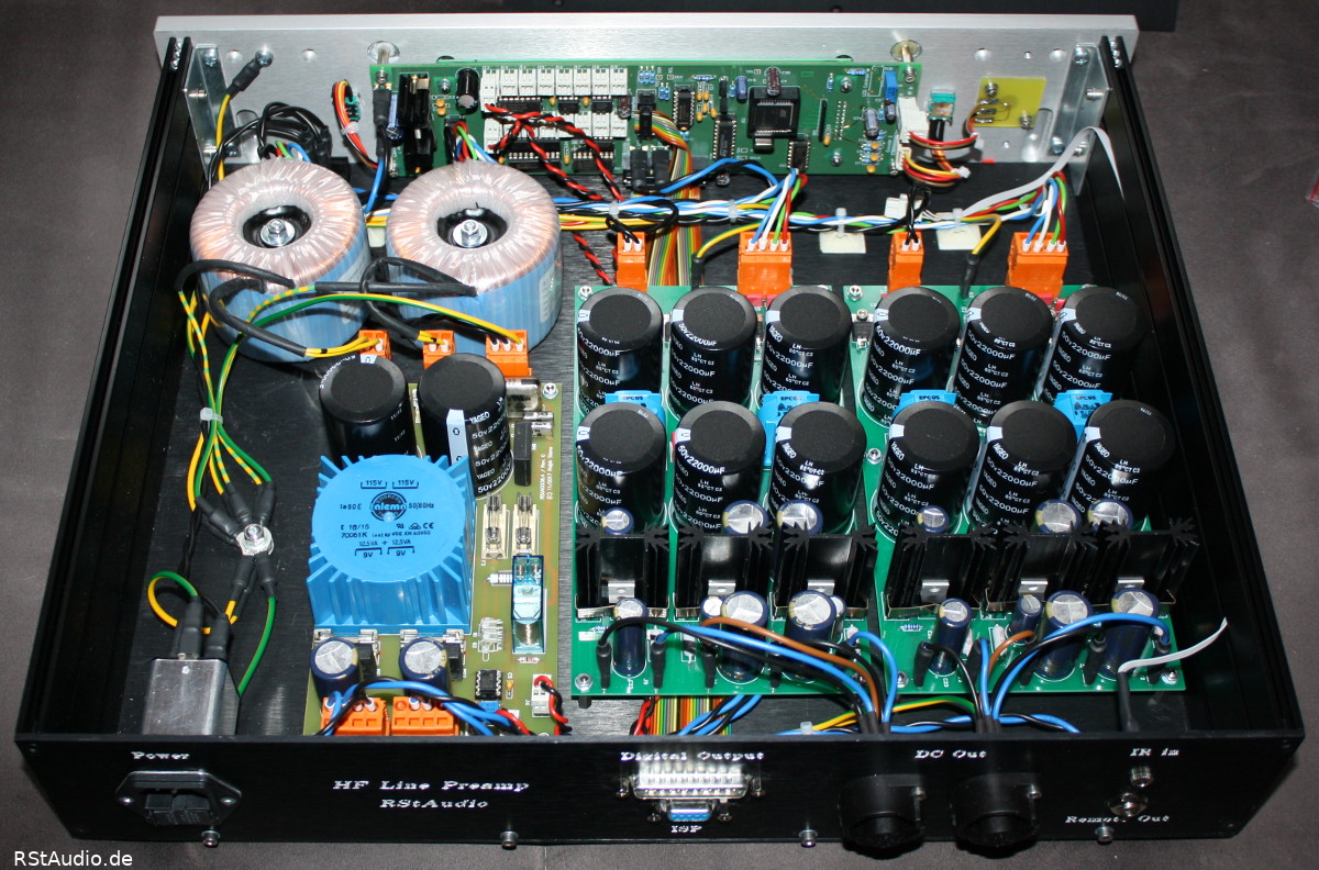
The Control Unit contains all circuit parts that are not directly related to the processing of audio signals. In particular, the mains voltage is only fed into this part of the preamplifier.
The 230V/AC enters the housing via a mains filter with integrated fuses. This voltage is fed to the first circuit board via the mains switch. There you will first find another capacitance filter and then a 230V/AC DC filter. Behind these filters are two external toroidal transformers for generating the audio voltages and a toroidal transformer on the board for the digital supply voltages. All transformers are also individually fused. The digital voltages are rectified directly on this board. Two unregulated DC voltages are available – μC-board supply and relay voltages.
Furthermore, there is a circuit for determining the current phase position on this board. This was the first time I really thought about the functional safety of such a circuit and redesigned it as a result. I now use a glow lamp that can be switched between a phase and earth by the microcontroller via a relay. If a defect occurs here, the probability of danger for the user is extremely low.
Of course, the safety of the user is primarily ensured via the earthing of the enclosures.
The glow lamp is monitored by a photo resistor whose signal is connected to the μC circuit board via a comparator. When the phase position is queried, the controller closes the relay and evaluates the output signal of the comparator. The relay is then switched off again.
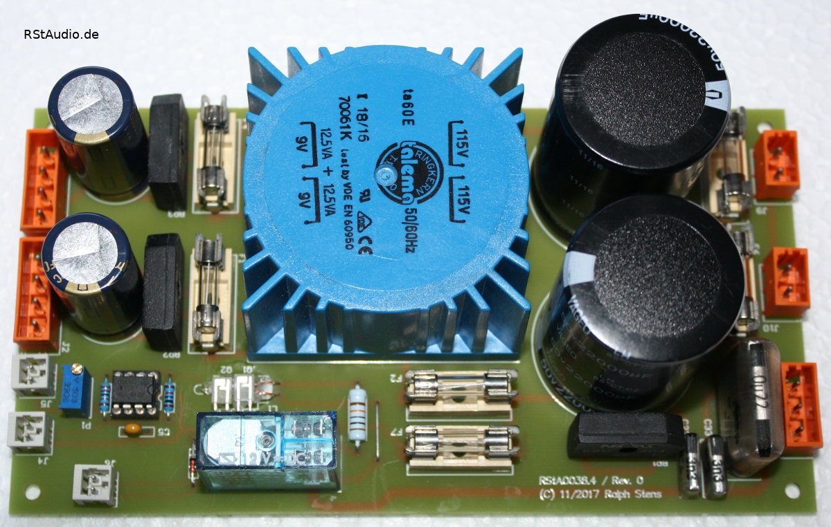
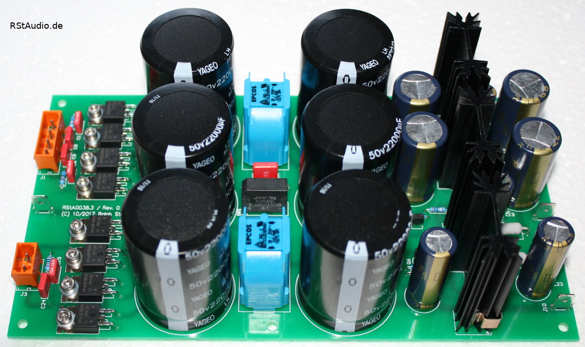
Two other PCBs in this unit are responsible for providing the unregulated DC voltages for the audio circuit parts. Here I use proven technology. Behind the secondary windings of the toroidal transformers are snubber networks. This is followed by the rectifiers with discrete ultra-fast soft recovery diodes. This is followed by CLC filtering with 22mF capacitors. Behind these filterings are capacitance multipliers with additional low-pass filtering towards the output. From here, the DC voltages are fed into the audio unit via a cable.
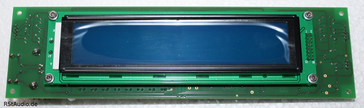
Another PCB is the controlling microcontroller system, together with the LC display as a unit, screwed behind the front panel. I use my tried and tested Atmel AT89C51ED2 x51 controller here again. The communication to the audio unit runs only via serial protocols – I²C and SPI – and is in sleep mode as long as there is no switching. The preamplifier is operated with the help of two rotary encoders or an RC5 remote control and the display with 2 lines and 20 columns.
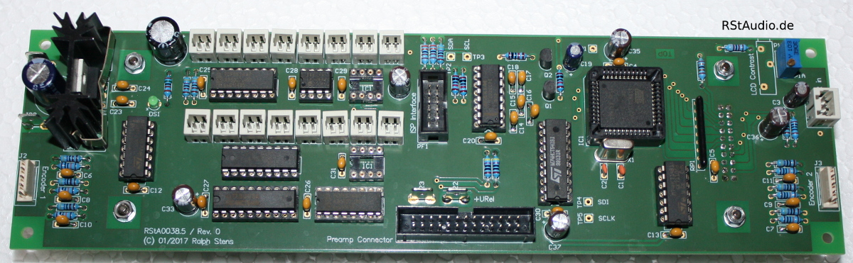
The LC display has 2 lines and 20 columns with a character height of 12.7mm. As mentioned above, it is screwed directly onto the back of the μC board.
The picture below shows the complete control unit with the cover removed. All the circuit boards and components described above are clearly visible.
Audio Unit
23-01-2022
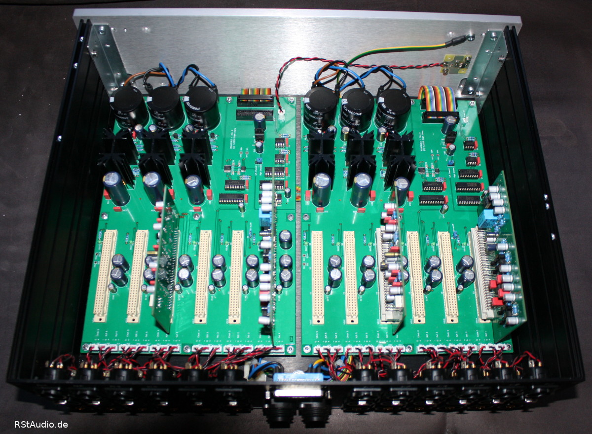
The audio unit is almost completely filled by 2 bus boards. On these boards are discrete voltage regulators for the voltage supply of the analogue circuits and six slots for audio boards. For each of these 6 slots, 2 inputs and one output are placed on the board. Thus, there is no wiring to the audio boards.
Furthermore, each bus board has a digital circuit section for controlling the relays and the digital potentiometers. The transition from the μC-system to the analogue circuitry is done via a potential separation with components from the ADuM-series of Analog Devices.
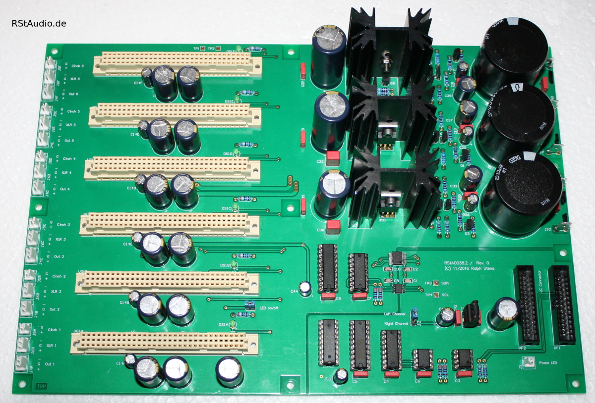
There are two types of audio boards. Both are identical in terms of their circuit topology. The balanced input is switched directly to the first amplifier stage, the unbalanced input is first balanced with the help of a DRV134/135. Then the balanced signals are fed to the amplifier formed by an OPA1632. The amplification is set to 6dB. After this amplifier, the balanced signal is adjusted to its final volume by a digital potentiometer – the MUSES72320 is used. The last stage is a balanced output driver.
The two boards differ in terms of technology. The first is equipped with 2 operational amplifiers connected in parallel per signal phase (2× OPA1612).

The second board has implemented discrete diamond buffers with servo controllers instead. The OPA1632 and the MUSES72320 are placed on the back of the board.

The picture below shows the complete audio unit with the cover removed from behind. A total of 4 audio cards are plugged in.
Installation of the Cabinets
23-01-2022
As in the past years – except for the active absorber – I used cabinets from HiFi-2000. For the control unit I use a cabinet with 80mm inner height and for the audio unit one with 120mm. I need the higher enclosure to get space on the rear panel for all the connectors. Of course, the plug-in cards also need some space in the height.
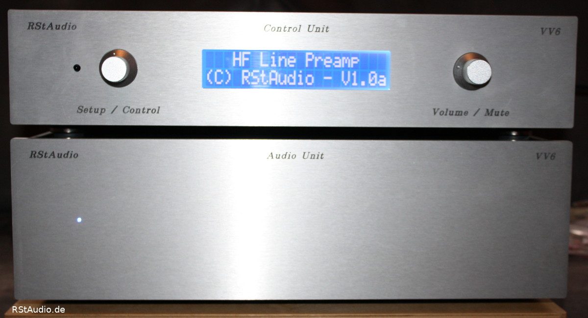
The view from the front can be seen at the top of the page. The LC display is placed in the centre. To the left and right of it, you can see the two rotary encoders. On the left side you can see the integrated IR receiver.
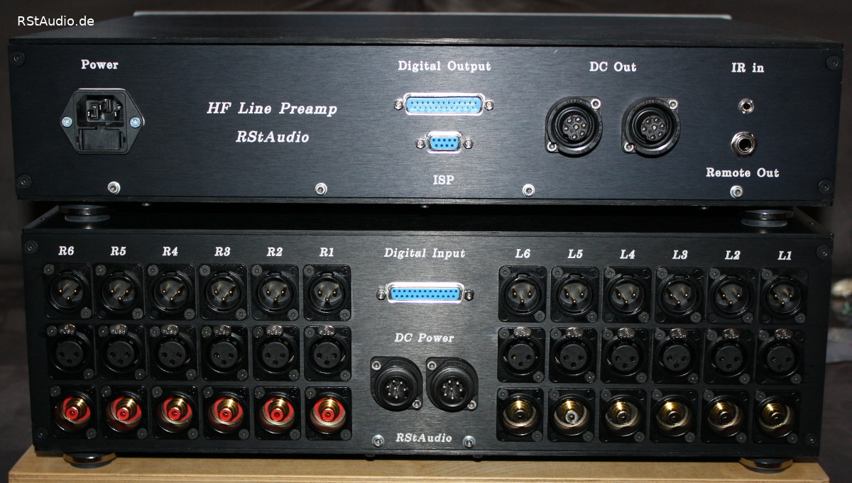
The rear view can be seen in the following photo. For each channel you can see the two inputs (XLR & RCA) and an XLR output. The digital signals and the digital supply voltage are transmitted from the Control Unit to the Audio Unit via the 25-pole Sub-D connection. The Hirschmann industrial connectors are used to connect the analogue voltages between the two housings. The two connecting cables required for this are manufactured in-house.
The control unit also has a 9-pin sub-D socket for transferring the software to the microcontroller (ISP – In System Programming), an input for an external infrared receiver (IR) and the output for the remote voltage (see above). Natürlich befindet sich hier auch der 230V/AC Netzspannungseingang mit Filter und integrierten Sicherungen. Der Netzschalter ist auf den Photos nicht zu finden, er befindet sich vorn rechts auf der Unterseite der Control Unit.
Audiophile Performance
23-01-2022
How do the two audio modules compare to the VV5? I have to say surprisingly well! However, I have only listened to one afternoon and so the preamplifier modules are still far from being played in. So my friend Heiner will run them for a while and then we will both report back.
03-04-2018 / Ralph :
My first positive impression was not deceiving, in the meantime I would have a hard time deciding between this preamp and the VV5. The richness of detail of both preamps is comparable, but there are slight tonal differences. These, however, go in the direction of taste and I wouldn’t know which I would ultimately choose. All in all, a pretty successful construction that shows what modern audio IC’s are capable of nowadays.
23-04-2018 / Heiner :
Now that I have owned the VV6 for some time and have listened to it for many hours, here is my impression: Actually, all preamplifiers should sound the same or very similar, as the measurements suggest. Everything is very good and deviations are so small that our hearing can’t understand them. Yes, but it is not like that. The VV6 needs 1-2 hours to warm up. After that, it just plays in a way that makes me want to listen to music. I listen to CDs from beginning to end and no longer just put on my “test music”. Complex structures (e.g. tutti in classical music) are fanned out so clearly that they no longer seem complex at all. Or rather, it must be child’s play to dissolve them and present them as musical events. The VV6 can make every instrument sound natural, just as it does with small ensembles. The three-dimensionality is very credible. It’s really fun and listening to music is beautiful and musical and natural. I have treated my living room acoustically quite well and the reverberation times are reasonably linear across the frequency response. In this environment, the VV6 is now running and always gives me pleasure to listen to.
It should be added that we both – and consciously independently of each other – prefer the module with the Diamond Buffer.