… life, the universe and everything …
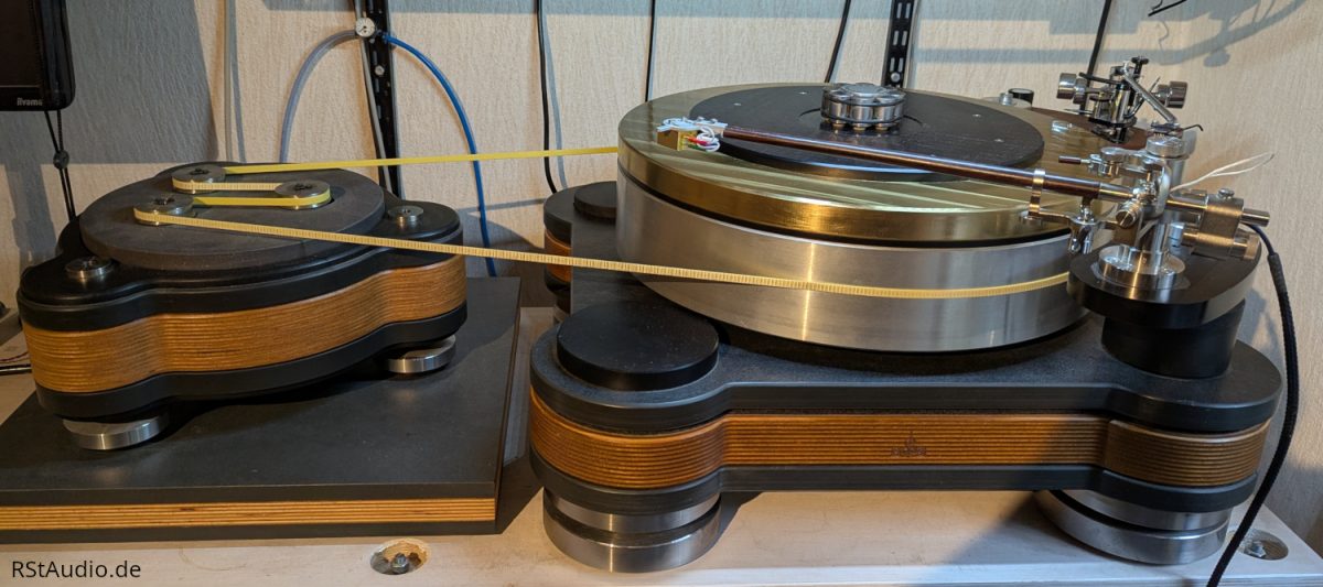
Table of Content
Introduction
23-08-2017
When I met Jürgen B. in December 2012, I had already been working on the motor control system for a turntable for some time. I had a DIY player with Scheu components in use with an ebmPapst motor. To measure the rotation speed I modified the Scheu platter with markers. Everything was functioning to my satisfaction and as a next logical step I thought about the development of a complete record player. I had some nice ideas, but my background is electrical engineering and so I hadn’t the needed professional knowledge to fullfil my own requirements. But with Jürgen as my partner we both have enough expertise for such a project.
What we didn’t expect is that we had to learn so much about an assumed simple topic. At least we need around 5 years to finish this project.
Some of the boundary conditions for the development of my record player are naturally fixed for me from the beginning:
- mass player with a turntable weight >25kg
- 42cm diameter of the turntable with an as high as possible moment of inertia
- vertical air bearing
- external motor case with 3 motors
- speed measurement / speed control
- possibility to assemble a minimum of 2 tone arms
- On the Fly vertical adjustment of the tone arm bases without an arrester
The large diameter of the turntable limits the operation of tone arms so that only 12″ types are usable. This might for many of you certainly a disadvantage, but for me it is a logical consequence of my preference for longer tone arms. The main part of the weight, of the at least nearly 40kg heavy turntable, is located at the outer edge which benefited the moment of inertia.
Who is asking himself why I choosed a diameter of 42cm, has obviously not my age and hadn’t studied electrical engineering, mechanical engineering or computer sience ☺. 42 is the answer to the ultimate question of life, the universe and everything – more details you can find here.
At the 16-08-2017 this player had finally replaced my old DIY Scheu construction.
Record Player
22-02-2026
The buildup of this player consist of a series of materials which we choose through experiments. We use C45 steel, wood, schist, aluminium, gray iron and different synthetic materials. The production technologies of this parts are from waterjet cutting over CNC milling to 3D laser sintering. But above all, there is a lot of manual work in the drive, which was perfectly carried out by Jürgen. The surfaces of the raw materials are not changed – e.g. no epoxal or chrome – so that the specifically characteristics of the materials are not influenced and therefore garantee the perfomance of this materials. Where we had to protect a surface we used a special wax.
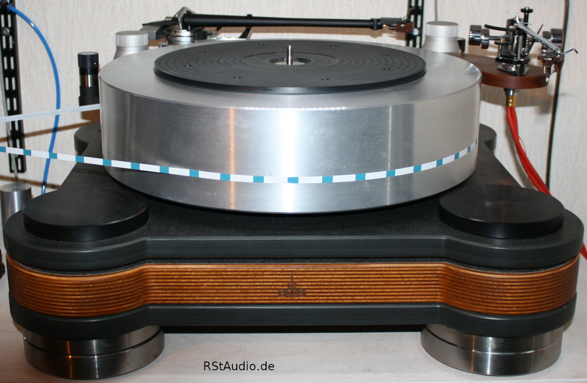
A precision bearing with a lifetime solid lubrication and an extra thick precision-ground spindle takes over the horizontal bearing of the turntable. Three air bearings adapted to the load capacity of the overall weight of the platter with an air gap of 5μm are responsible for the vertical bearing. With this implementation we have no noise and no slip-stick effects from the bearings.
The platter itself is made of aluminium and has a weight of nearly 40kg. To measure the rotational speed markers are placed at the bottom side. As I wrote above the diameter is 420mm. The bigger part of the material is placed at the outer edge which gives us as much as possible inertia. The record disk itself is placed on an exchangeable base, so that we have the possibility to experiment with different materials. I selected vinyl (polyvinyl chloride – PVC) as a starting point. The bolt is placed on top of the platter and has no direct contact to the bearings.
The player sits on top of 4 in the hight adjustable bases. Each base consists of two parts which are only connected via a steel ball, finally the complete player stands on that 4 balls. In each lower part of a base an additional damper is mounted.
Update February 2026
Since delivery in 2017, two very unsightly dents have “adorned” the upper edge of the aluminum plate. They were caused by a car accident in which the unsecured, very heavy plate flew through the interior during an emergency brake maneuver. One should be aware of the inertia of such a component and never transport it unsecured!
The idea of milling off the top of the aluminum plate and replacing it with a corresponding brass part has been around for a long time. In addition, it always bothered me that the center pin, which is fixed to a small round stainless steel disc, only rested loosely in a corresponding recess in the plate. Unfortunately, this plan was never implemented in all those years.
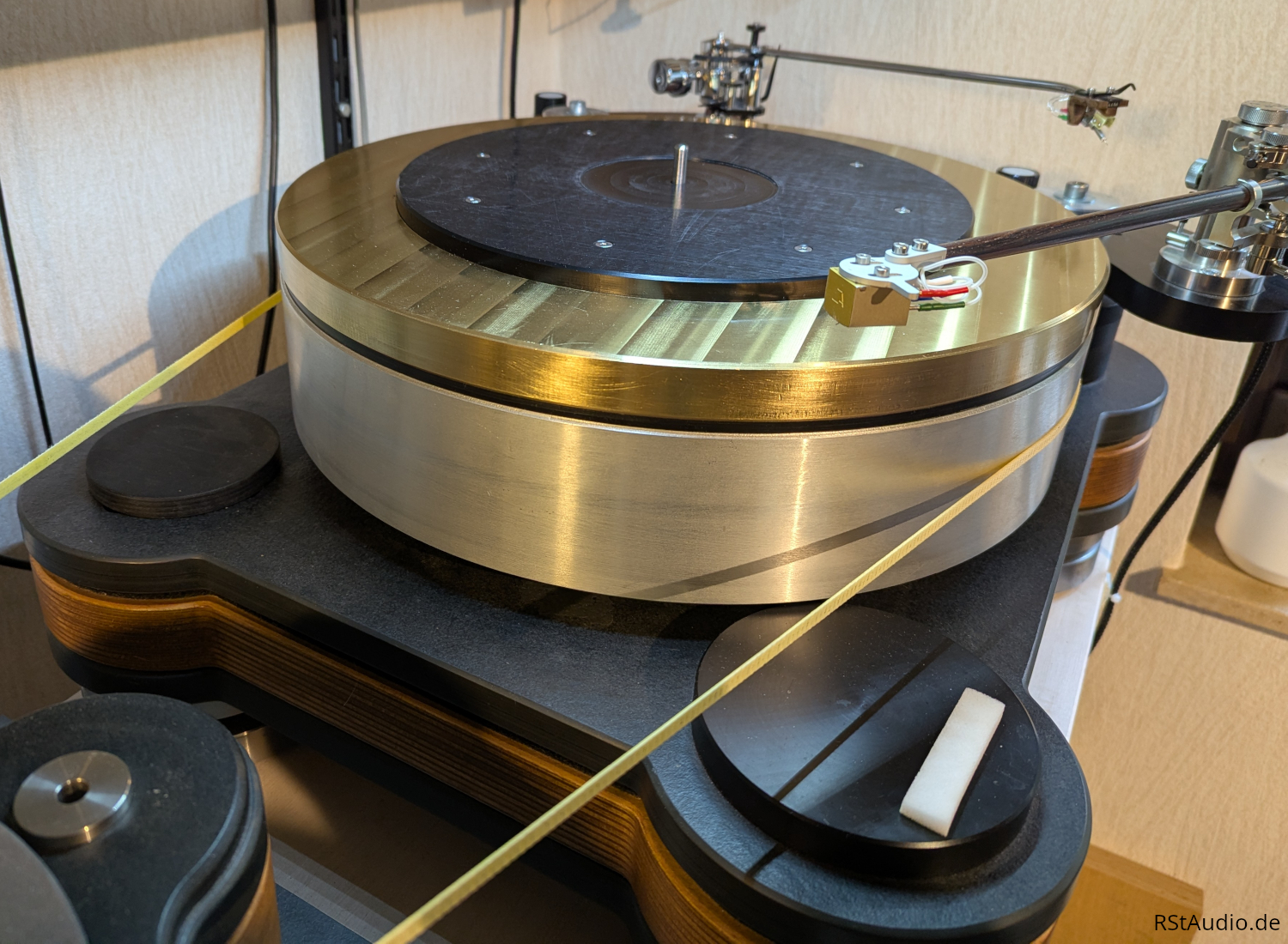
Since mid-2024, my friend Guido has been taking care of all my mechanical needs relating to the drive. At the beginning of September 2025, we sat down together and considered how the quirks could be eliminated using the above plan. The center spindle was also to be fixed in place. The result was a layered construction of the platter:
- 80mm high aluminum plate
- 5mm high POM disc
- 24mm high brass plate
- 10mm high record support made of POM
The three plates made of aluminum, POM and brass are aligned with each other by a stainless steel centering piece. The centering piece closes at the upper end with the center pin and fits into a corresponding slot in the aluminum plate at the lower end. The record support is screwed onto the brass plate and has a hole in the center with the same diameter as the center pin. This clamps the centering spindle from above, so that the center pin is (finally) firmly in place.
The total mass of the platter has increased significantly due to the use of brass (specific weight: approx. 8.4 g/cm³) and now stands at 56kg, even though the aluminum platter (specific weight: approx. 2.7 g/cm³) has lost 20mm in height. The three air bearings can easily support the additional weight. To be on the safe side, however, I increased the air pressure slightly. There is also no need to worry about the horizontal bearing with its thick shaft due to the additional weight. The drive also handles the additional mass with ease.
Apart from these two quirks, I have always been very pleased with the turntable. However, the current platter with its colored layers looks simply stunning! The turntable has also gained in terms of sound quality, even if only by a slight margin.
#42 Record Player since February 2026
Tone Arm Bases
19-03-2022
As you can see on many other heavy mass record player it is possible to assemble up to four tone arms on my player. One in every corner of the base. The tone arm is bolt on an universal constructed arm. To achieve the correct distance between the tone arm pivot point and the midpoint of the turntable the base arm must be turned in the correct position around it’s clamping bolt.
My preferred pick-up respond very sensitive to the VTA adjustment and therefore you can hear tonal differences between normal vinyl and such with an audiophile weight which are thicker.
VTA: Vertical Tracking Angle – more here
How to adjust the tone arm correctly for this situation? For the bigger parts of my normal vinyl or to hear my thicker audiophile vinyl optimally. Or a compromise between both? Finally I have spend a lot of money for my tone arm and my pick-up and I want to have the optimal setting for every vinyl I want to hear.
The solution is an on the fly vertical adjustment of the tone arm base without an arrester. Exactly such an adjustment we have realized. The construction of the mechanic uses an anti-backslash gearing mechanism with a repeatable adjustment of the height per turn of the tuning knob. The zero-point of the basis can be moved within ±12mm in the height which is enough for every situation.

In order to position the height exactly according to the thickness of the record, an appropriate measuring device is still missing.
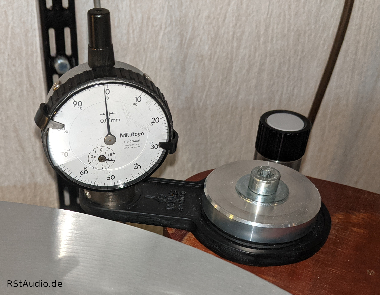
I align the arm exactly horizontally with the help of a cross laser. Starting from this basic position, I can then reproduce the VTA positions for records of different thicknesses with the help of the measuring gauge. For my pick-up, the arm must be set a little higher at the base.
Pressure System
13-10-2017
At a well known heavy mass record player with magnetic bearings I measured the remanent magnetism with a simple compass on the surface of the turntable. In doing so I saw noticable movements of the needle. This was the reason why I decided years ago to use an air bearing. I don’t want to have a magnetical field nearby my pick-up.
As is known compressed air is a very expensive energy form and if you want to build the system as perfect as possible the effort is respectively high. The system I have actually in use is a compressor, an air dryer, a 14l big reservoir with an integrated pressure reducing valve, a proportional valve to set the flow rate electronically and a 0.2l settling vessel directly implemented in the player. Thereafter the compressed air is distributed via a loop air line to the 3 air bearings.
Especially the air dryer is a very clever construction from Jürgen. A suitable systems is in a price range above 1500€. The solution comes from the automotive industry and is normally used in trucks. It is even a regeneration of the dryer cartidge integrated – as I said, very very clever.
Motor Case
18-10-2017
When I saw the 3 motor drive of the TW Acustic Raven Black Night from Herne/Germany, I knew that I want to do it exactly in this way at my own record player. A 3 motor drive with this arrangement is for me the correct way.
Even though the arrangement of the motors is the same as on the Raven Black Night, the rest of the motor box is more complex. The middle motor can be moved by turning a knob to optimise the pre-tension of the tape – which I use instead of a belt. This is much finer to adjust than simply moving the heavy motor box.
In addition, the 3 feet of the motor box can be adjusted in height. In this way, you can not only align the box exactly horizontally, you can also adjust its height to the centre of gravity of the platter.

The pulleys are precision-turned and have a central collet towards the motor shaft. This guarantees that they are exactly centred and run smoothly. The diameter of the pulley’s is chosen so that the motors are in the optimal working range at 33.3rpm – the lowest possible speed at maximum torque (running noise minimised).
The motors used are dismantled before use and their original bearings are replaced with precision bearings. This gives them a significantly improved running smoothness. In addition, each motor is individually damped inside the motor box. The motor box itself is lined all around with damping material. With these improvements, the drive with 3 running motors is no longer audible even from a short distance.
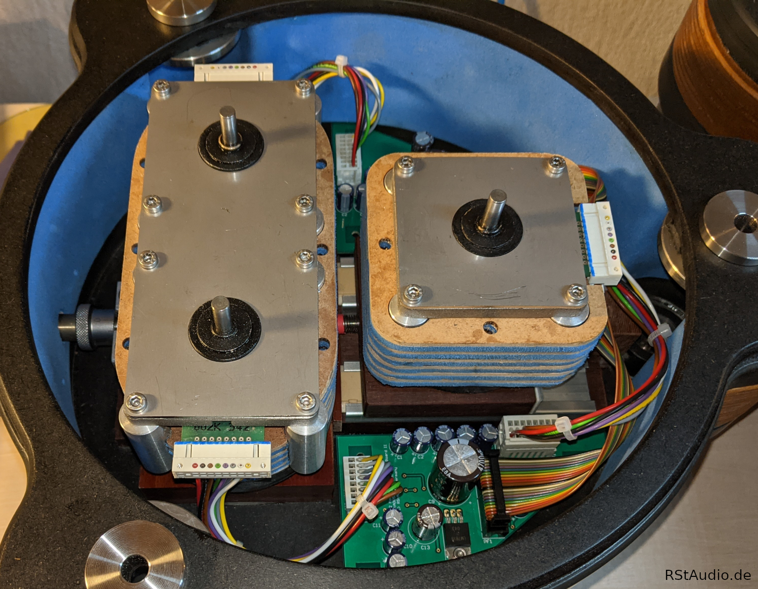
An absolutely successful and impressive construction by Jürgen!
The signals are distributed with the help of the two circuit boards. The many capacitors support the operating voltage directly on location. In addition, driver components for the control signals are integrated (SMD components on the bottom). The motor socket is connected to the motor electronics via a 25-pole Sub-D standard cable. The socket for this is located on the bottom of the box in a small additional housing from a 3D printer.
Drive Electronic
21-11-2021
Basis of the drive electronics is a C8051F120 x51 microcontroller from Silicon Labs which I operate with the maximum internal clock of 98MHz. It is operated with a rotary encoder and an OLED (Organic Light Emitting Diode) display with 2 lines and 20 columns. The software has grown a lot over the years and got lots of features around the operation of a drive.
Among other things, I store the run time of up to 5 pickups. This is not 100% exact, but in any case much more accurate than all estimates.
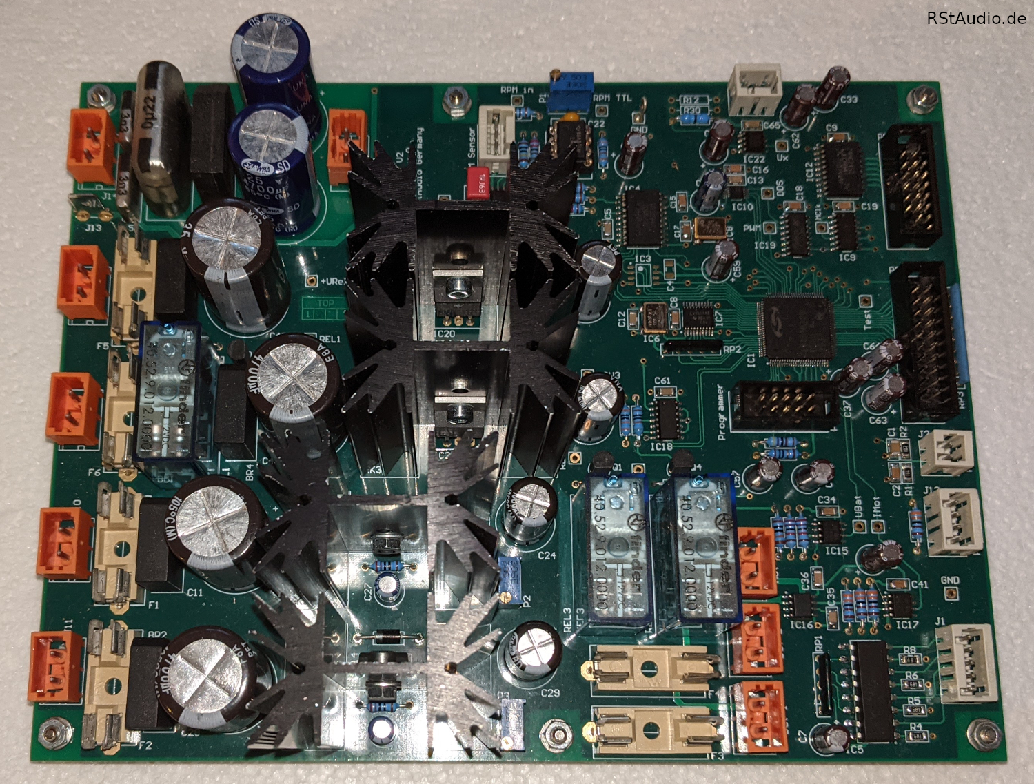
The motors we use have their own integrated electronics and require two status signals and a square wave signal whose frequency determines the speed for drive. This frequency is generated from a quartz reference by means of a DDS chip. The output frequency for the speed is set in the chip by a 28-bit register, which corresponds to an extremely fine frequency resolution.
Optical markings are mounted under the platter which are scanned by a reflective encoder. With the resulting measurement signal and a 25MHz reference frequency, the speed is measured with very high resolution in a 32Bit counter register. However, regulating the speed of a disk with such a high mass inertia has proven to be counterproductive. The speed is extremely stable even without it. The target speed of the motors is calculated by the software from the geometry data of the disk drive and can be adjusted slightly by the operator.
During my experiments with the ebmPapst motors, I found that they run much smoother when powered from a battery. Since the nominal operating voltage is 24V, I connected two 12V/7Ah lead-acid batteries in series. These batteries are gently charged when the drive electronics are switched off. At every start of the motors the battery voltage is measured first. If it is below a preset value, the drive cannot be switched on. This prevents a deep discharge of the batteries, however, this has never happened in all these years and I still use the first set.
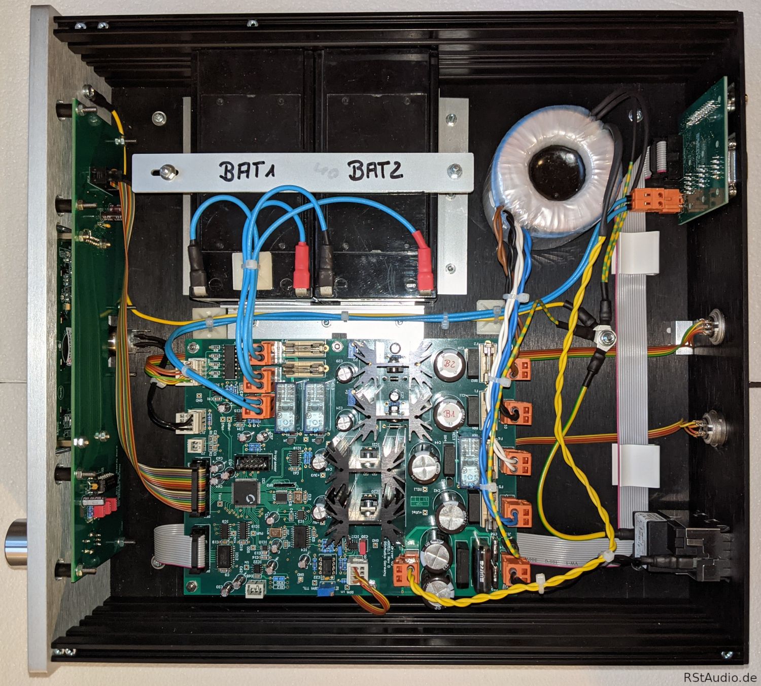
On the photo above you can see the inside view of the motor electronics. In addition to the electronics board there is a PCB with the display and the encoder screwed directly behind the front panel and a small distribution board for the motor signal behind the rear panel. You can also see the two batteries.
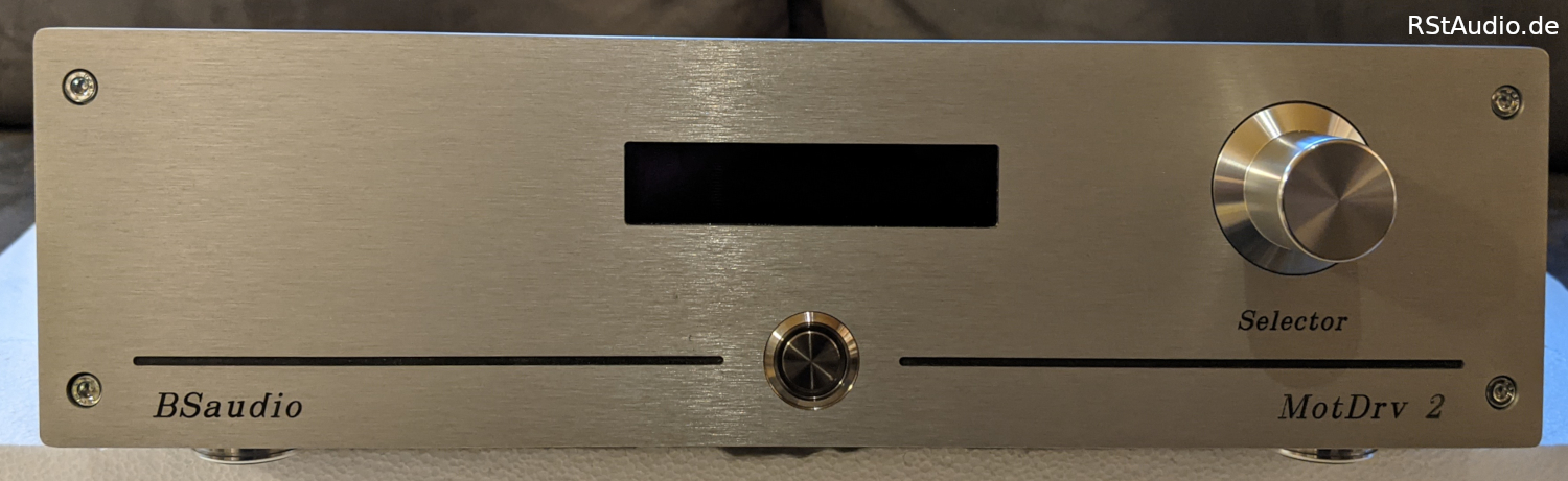
There are not many operating elements on the electronics. The electronics are switched on and off with the pushbutton. The display (2 lines and 20 columns) and the rotary encoder are responsible for the actual functions.

On the left side of the rear panel is the 230V/AC socket with filter, fuses and switch from Schurter. To the right is the input for the speed signal.
The connector to the right of it, labeled PickUp No., is only useful in conjunction with my preamps. The preamplifier transmits the number of the currently selected pickup. I then no longer need to manually tell the motor electronics for which pickup the current run time should be determined.
The motors are connected to the Sub-D connectors on the far right. You can either connect each motor individually via the corresponding 9-pin Sub-D or, as in my case, all 3 motors together via the 25-pin Sub-D connector.