Table of Contents
- Introduction
- What exactly does azimuth mean for the pickup?
- Required Hardware and Software
- Settings of ARTA
- Measurement of the Phono Preamplifier
- Azimuth Measurement
Introduction
15 September 2024
My first record player, a Dual, still had a factory-fitted pickup. But already with my second turntable, a Thorens with a SME Series III tonearm, I had to install and adjust the pickup myself. Over the decades I have installed and adjusted many cartridges. I think I have mastered this profession halfway.
In the German lp Magazin 05/2020 there is an article about a tool for adjusting the azimuth with a price that makes you dizzy. The author wrote a few lines similar to mine above, also he was of the opinion that he can install a pickup correctly.
I’d rather not tell you how many pickup installations I’ve checked with the device where my “toe-in” setting was way off the mark.
Holger Barske, lp Magazin 05/2020
I had a deja vu when I read the article. Already weeks before my friend Heiner had pointed out to me that the azimuth can only be adjusted correctly with a measurement and that it will have partly dramatic consequences on the sound.
What exactly does azimuth mean for the pickup?
15 July 2020
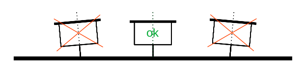
When looking at the lowered pickup from the front, the needle should be at an exact angle of 90° to the record. When installing the pickup you can usually only orientate yourself by the edges of the housing. But in the end you have to be sure that the manufacturer has installed the needle correctly. If you look at it realistically, an exact optical control of the azimuth is nearly impossible.
However, it is electrically possible to adjust the azimuth exactly. To do this, one measures the two channels of the pickup with a suitable measuring signal and compares the levels with each other. If everything is adjusted correctly, the deviation of the two channels should be as small as possible.
Required Hardware and Software
15 July 2020
Unlike the very expensive tool discussed in the lp Magazin, our approach burdens most audiophiles with a cost factor below 100€ – if not everything is already available at home.
So what do you exactly need to be able to carry out a reliable azimuth measurement?
- a PC with a halfway reasonable sound card
- ARTA – Audio Measurement and Analysis Software
- a test record with suitable test signals
I think most of us will have a PC and a sound card will also be available. You connect the inputs of the sound card to the tape or preamp outputs. Of course you can also connect your phono preamp directly to the sound card.
ARTA can be downloaded from the homepage. The demo version is completely sufficient for the measurement described here. However, you cannot save your measurement results with it. But the license is very cheap and should be feasible.
What is missing now is a record with test signals. I use the test record TLP-1 from Sperling Audio. You can buy them for relatively little money in the shop there. This record has a 1kHz stereo tone with 33.3rpm on one side and a corresponding signal with 45rpm on the other side. The signals have a long running time and so you can concentrate on the measurement in a relaxed atmosphere. If you use conventional test records, the useful signals are usually too short.
Unfortunately, support for ARTA has been discontinued. REW is available as an alternative.
Note:
- ARTA selling will be stopped on March, 30, 2024.
- The firm ARTALABS be closed in April or May 2024.
- The ARTALABS web site will be active until February, 2025. The last version and support files will be available for download.
- I hope that you will be able to use ARTA software on Windows for many years (while Windows support 32-bit programs).
Best regards, Ivo Mateljan
Settings of ARTA
15 July 2020
Before you can start measuring the azimuth, you will first have to make some basic settings in ARTA.
First you have to set the sound card, or more correctly the drivers of the sound card, in the AUDIO HARDWARE SETUP of ARTA. This is described in detail in chapter 1.4 of the manual.
Afterwards, the calibration of the inputs and outputs of the sound card is carried out. This is covered in the chapter 1.5 CALIBRATION. ARTA uses the left channel for signal generation for its measurements. First of all, chapter 1.5.1 describes how to adjust the output signal with an external measuring device. However, we are not really interested in the absolute measured value, for the measurement of the azimuth an exact relative measurement is completely sufficient.
What exactly does that mean?
How exact the output level of the sound card is has no influence on the measurement of the azimuth. It is important that both input channels match as exactly as possible. Furthermore, our measurement signal does not come from the sound card but from the test record.
So you can skip the instructions under 1.5.1 Calibration of Soundcard Output Left Channel and calibrate the two inputs with the uncalibrated output signal of the left channel of the sound card as described under 1.5.2 Calibration of Soundcard Input Channels. This means that the measured values shown below certainly have a deviation from the real value, but the only important thing is that both channels behave the same and show us an exact difference. And this is exactly what is achieved by carrying out the calibration as just described.
Of course it is also not wrong if you have an appropriate measuring device available to calibrate the output of the sound card as well.
Adjusting the input channels of my ADC (RME ADI-2) showed that they have a deviation of 0.036dB from each other – a very decent value. This result is included in measurements after calibration by ARTA.
ARTA has a very well done, even if very academic, documentation in English. The configuration should be easy with it.
Measurement of the Phono Preamplifier
04 October 2020
But not only with the soundcard used for the measurement, both channels must have exactly the same amplification factor, this should also be the case with the phono preamplifier. Actually, this is a common feature of our high-end devices, but unfortunately I have experienced it much too often differently. Since I have built my own phono preamplifier, I know that it fulfills this requirement.
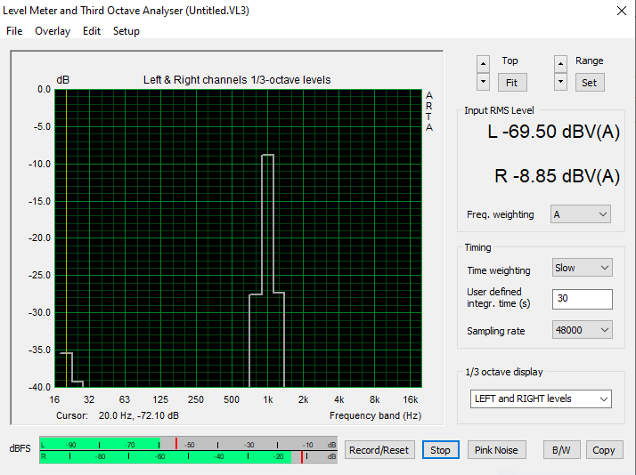
If you are unsure, you can also measure this with ARTA. For this purpose you use the test record and in ARTA the measurement described below. You connect only one channel of the pickup with your preamplifier – which one is not important – and measure the level. Afterwards this socket is connected to the other channel of the phono preamplifier. The now measured level should correspond exactly to the level of the first measurement. If this is not the case, the difference describes the deviation between the two channels at the measuring frequency, in my case 1kHz.
As a demonstration I have measured the two MC inputs of the DPV1 in the way described above. As input signal I used the right channel of the respective pickup.
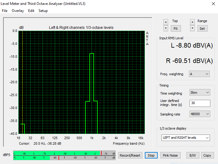
The two channels of the first MC input run with a difference of 0.05dB. You can be very satisfied with this.

The channels of the second MC input also have the same deviation (0.05dB). However, here we have a level about 0.5dB higher. This is due to the use of 2 different pickups and a different amplification factor.
If you have determined a deviation between the channels of your phono preamplifier, you can use the measured difference as correction value when determining the azimuth.
Azimuth Measurement
19 October 2020
To measure the azimuth, open ARTA and select the menu item Tools and the measurement Two channel level meter. The dialog box Level Meter and Third Octave Analyzer opens, which we use for the azimuth measurement.
In the dialog box on the lower right side, under 1/3 octave display the option LEFT and RIGHT levels should be selected. If this is the case put on the test record and press the button Record/Reset. This starts the measurement and after a short time you get a stable measurement value which is displayed graphically and as a numerical value in the upper right side of the window. This measurement / dialog box is described in the current ARTA manual starting on page 177.
Ideally, the values for the left and right channels are equal. If they differ noticeably the azimuth is not correct and the system must be turned to the left or right.
When measuring, you should also pay attention to the level. If the input signal is clipped, you cannot expect a reasonable measurement result.
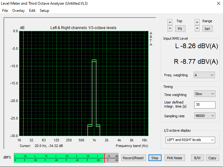
The picture above shows the measurement of the MC1 input before the azimuth adjustment. The left channel is 0.51dB louder than the right channel. The value is not that bad at all. It speaks for the mounting of the pickup at the manufacturer and for my adjustment.

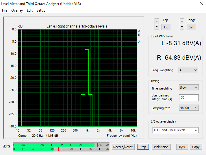
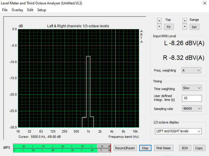
After the adjustment I have a measured deviation of 0.07dB. If you include the difference of the two MC1 channels in this result, there is a discrepancy of 0.02dB. With such a small difference between the channels, one can assume that the needle is exactly perpendicular to the record.
The original difference between the channels was only about 0.5dB. I had therefore not really expected any improvement. I would not describe the benefit from the exact adjustment of the azimuth as dramatic, but as more than significant.
After the adjustment there is a deviation of 0.06dB for MC2. If the difference between the audio channels is also taken into account, the deviation between the channels is 0.01dB. The audiophile result is comparable to that of MC1.
So my recommendation is this:
Take care of the azimuth, otherwise you leave a part of your pickup’s potential unused!