
Table of Contents
Correct AC Phase
13-07-2021
As you know, in most countries you can insert a mains plug into the socket in two possible positions. There should actually be no difference between the two positions, but not all devices are symmetrical on the mains side. This is especially true for appliances with the two-pin Euro plug (EN 50075, also known as Type C “CEE 7/16”, 250V/2.5A). For this reason, it is worthwhile to carry out the following measurement on your audio equipment and to insert the mains plugs “correctly” into the socket according to the measurement results.
- All connections of the audio device to be measured to the other components of the audio system must be disconnected. Only the mains plug itself may be connected to the device.
- With a standard digital multimeter, measure the AC voltage between the protective conductor of the socket and a ground point of the audio device. The easiest way to do this is to use the external connection of a cinch plug.
- After this first measurement, switch off the device and turn the mains plug in the socket by 180°. Then switch the unit on again.
- Now measure the AC voltage again as described in 2.
- The measurement with the smaller voltage is the correct audio position of the mains plug.
As you can see, you don’t need an overpriced phase meter from the Audio trade. All you need is a cheap digital multimeter from the electronics market. The nice side effect is that you can also carry out various other measurements with this measuring device.
230V/AC DC-Filter
13-07-2021
I first found the description of a DC filter at www.saque.de.
I first experienced the sometimes “significant” changes that occur when using DC filtering in the 230V/AC supply line of an audio device with my small Zen power amplifier. Since then, the filter described below has been used in every mains supply line of my DIY audio components.
The physical effect of this filter is easily explained :
If you analyse the voltage from the socket more closely, you can get some frightening results depending on the geographical location and time of day. The voltage is not always sinusoidal and often contains DC voltage components. It is precisely these DC voltage components that we are concerned with here. They cause a premagnetisation of the transformers in the audio devices, which can be very noticeable in the sound of the device. The filter described here “blocks” these DC components and thus reliably prevents the negative effects of the pre-magnetisation of the mains transformers – so there is no voodoo involved at all!!!
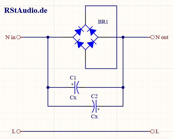
The circuit of the described DC filter can be seen in the picture above. The capacitors (C1 & C2) block the DC component and the diodes of the bridge rectifier (BR1) ensure that the voltage at the capacitors cannot become too high (here 2 diode paths ≈ 1.2V). I have connected two capacitors anti-parallel, which has the advantage that the capacitance values add up. However, you have to accept that during a half-wave of the mains frequency, one capacitor is always wrongly poled. From my experience, this works well as long as the maximum voltage is limited to 1.2V and the capacitors have a dielectric strength of at least 25V. If you want to be on the safe side, you should connect two capacitors in series (either both negative poles or both positive poles together) and thus obtain a bipolar capacitor at the expense of the capacity (it is halved).
When dimensioning the filter, one must assume that the voltage at maximum current across the capacitors must remain lower than the diode voltage. I would like to carry out the dimensioning here using my Zen output stage as an example.
The transformer has 2× 15V / 5.7A on the secondary side. This results in a power of
![\[ P = U \cdot{} I = 2 \cdot{} 15\mbox{V} \cdot{} 5.7\mbox{A} \approx 171\mbox{VA} \]](https://www.rstaudio.de/wp-content/ql-cache/quicklatex.com-7b3bf7f907ca1147aae7021548f074be_l3.png "Rendered by QuickLaTeX.com")
This results in a current on the primary side (if the transformer is assumed to be loss-free) of
![\[ I = \frac{P}{U} = \frac{171\mbox{VA}}{230\mbox{V}} \approx 0.74\mbox{A} \]](https://www.rstaudio.de/wp-content/ql-cache/quicklatex.com-914192fc2f8f693f88d7bd720f50e375_l3.png "Rendered by QuickLaTeX.com")
With two diodes in series, the resulting voltage across the impedance of the capacitors must be less than 1.2V. This results in
![\[ X_C \le \frac{1.2\mbox{V}}{0.74\mbox{A}} \approx 1.62\Omega \]](https://www.rstaudio.de/wp-content/ql-cache/quicklatex.com-b1031d8cc3638e86ae2218026ec882b2_l3.png "Rendered by QuickLaTeX.com")
From
![\[ X_C = \frac{1}{2 \pi{} \cdot{} f \cdot{} C} \]](https://www.rstaudio.de/wp-content/ql-cache/quicklatex.com-651b534006bb3da670ab501ec4f4c724_l3.png "Rendered by QuickLaTeX.com")
thus results for the capacity
![\[ C = \frac{1}{2\pi{}\cdot{} f \cdot{} X_C} = \frac{1}{2\pi{} \cdot{} 50\mbox{Hz} \cdot{} 1.62\Omega} \approx 1900\mu\mbox{F} \]](https://www.rstaudio.de/wp-content/ql-cache/quicklatex.com-22a92d3b94702fa7f9fde8038381dc43_l3.png "Rendered by QuickLaTeX.com")
However, if a capacitor with 1900μF is used, there is no reserve for the DC offset at the nominal current calculated above, since the voltage drop across the impedance of the capacitor is already so large that the diodes of the bridge rectifier become conductive. For this reason, you will have to choose a larger capacitance. In my Zen amplifiers I used 2× 10000μF. As a good guideline, one can assume the following rule of thumb:
per 100VA ≈ 10000μF
This dimensioning results in a voltage drop across the impedance XC of the capacitor of

This results in a blocking effect of approximately 1V (with 2 diodes in series) for the DC component in the 230V AC voltage.
For my Zen power amplifiers, the final value is
![\[ U_C = \frac{171\mbox{VA}}{230\mbox{V}}\cdot{}\frac{1}{2\pi{}\cdot{} 50\mbox{Hz} \cdot{} 20000\mu\mbox{F}} \approx 0.12\mbox{V} \]](https://www.rstaudio.de/wp-content/ql-cache/quicklatex.com-da9d31e88bb5b5eaee473831b61a12a1_l3.png "Rendered by QuickLaTeX.com")
Snubber Network
13-07-2021
If you operate a transformer together with a rectifier – which is the case with almost every power supply – a high-frequency oscillation usually occurs on the DC voltage. There are a few very good articles on the web that describe this effect and also derive theoretical and mathematical models of how to design a network that dampens this oscillation. Unfortunately, one needs exact data of the transformer and the rectifier diodes for these calculations. Determining this is not always easy.
On diyaudio.com you will find a very interesting discussion about the determination of the network parameters with the help of a test circuit whose detailed description can be downloaded as a pdf-file in the first article.
Simple, no-math transformer snubber using Quasimodo test-jig
I have built up the measuring circuit and installed snubber networks for the first time in my XA30.5 replica. The following two pictures show the measurement of the transformer without (left) and with (right) the adapted Snubber network for a secondary winding of my transformer.
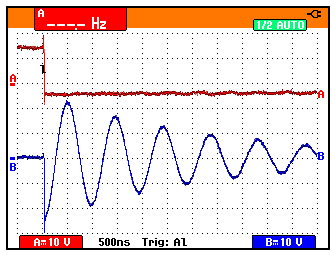
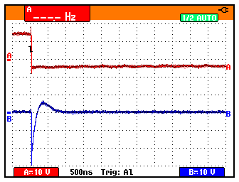
Channel B (shown here in blue) shows the oscillation at a secondary winding of the transformer. Note the horizontal (500ns) and vertical (10V) resolution.
Today I never build audio power supplies without snubber networks, they are an integral part of all my current circuits.
SB1pro & Vinyl Cleaning Liquid
13-10-2021
I am the proud owner of a SB1pro PWM (Plattenwaschmmachine) from Sven Berkner. The machine is a point vacuum cleaner where the cleaning fluid is applied at the touch of a button and the distance filament is adjusted automatically. I first became aware of the machine in 2010 when S. Berkner gave a lecture at the Analog Forum in Krefeld and I bought it some time later. I never regretted this step, the machine works practically and extremely reliably. In addition, Mr. Berkner has a really exceptional support. In the meantime, the machine has already received two improvements from the current series, which I also received free of charge – that’s what I call support!!!
Immediately after buying the machine, I used the cleaning fluid that came with it, but I was also looking for a suitable mixture to make the fluid myself. I didn’t have to search for long because my colleagues at the AAA regulars’ table had the right tip, which I would like to share with a wider audience.
| Menge / Quantity | Chemikalie / Chemical |
|---|---|
| 500ml | Dr. Wack 1:300 |
| 250ml | Isopropanol |
| 250ml | Ethanol |
| 2,5ml | 25% Ammoniaklösung / 25% Liquid Ammonia |
The Dr. Wack fluid is a windscreen cleaner concentrate Dr. Wack 1:100 super that you mix with distilled water in a ratio of 1:300. The distilled water should of course be as “clean” as possible, we use high-purity Ampuwa here. By the way, you can get the windscreen cleaner concentrate in car accessory shops.
Adding the ammonia solution in a ratio of 1:400 is a tip from Sven Berkner.
This liquid does an amazing job. I had a new record with obvious residues from the pressing process that the original cleaning liquid did not get rid of directly. After a soaking time of about 5 minutes with the above mentioned mixture, the trouble was over and it sounded exactly as you would expect from a new record. Even my records that were played wet up to 35 years can be played dry again without any noteworthy disturbing noises.
Addendum 2022
If you look only at the result, the above washing liquid works quite well. However, the high alcohol content has always bothered me, the liquid evaporates naturally very quickly with it. In addition, you have to count on a soaking time of 10 minutes for good washing results and work with relatively much washing liquid. This is not only very unpleasant from the smell, the machine also swims in cleaning fluid. All very unpleasant.
So I have looked around at the beginning of 2022 what is on the market and landed very quickly at the Last Factory. This company has an excellent reputation for decades for all kinds of tinctures around our beloved vinyl. There is a ready mixed cleaning fluid for record washing machines (LAST Record Cleaning Machine Fluid) in a canister with a content of one gallon (about 3.8l), the price here in Germany is acceptable.
I have been using this cleaner in my SB1pro for a few months now and am convinced in the meantime. The washing results are very good with a soaking time of 120s to 150s. Quite little liquid is consumed in the process, and the smell is also minimal.