!!! Please do not ask for Schematics !!!
As long as Nelson Pass does not publish the schematics, I will not pass them on, in order not to endanger the commercial success through unauthorised distribution.
Table of Contents
- Introduction
- Input Board with UGS5 Module
- Output Board
- Power Supply
- Inrush Current Limiter and Remote On/Off
- First Start-Up
- Changes to the Original Design
- Rebuilding to a XA30.8
Introduction
06-08-2021
I have had the circuit diagrams of the X.5 and XA.5 power amplifier series from Pass Labs for quite some time. Since I needed power amplifiers for the final extension of my loudspeaker system, it was obvious to choose a power amplifier from this series. Of course, this amplifier has to be able to drive my Quad ESL and should therefore be adapted to this loudspeaker in its performance data. I chose the XA30.5, especially as it is a stereo power amplifier and I have had very good experiences with the individual control of the speakers in the Stacked Quads.
The XA30.5 is a stereo power amplifier in push-pull class AB mode with a maximum output power of approx. 100W/8Ω per channel. However, if you look at the published data, it talks about an output power of 30W/8Ω. This is the output power in push-pull class A mode. It is therefore a power amplifier with a very high quiescent current. In addition, there is a circuit part that ensures that the output stage runs in single ended class A mode at low output powers.
At the input of the power amplifier is a UGS module with the famous SUSY (super symmetrical) circuit. The use of this circuit topology only really makes sense when balanced signals are used. Consequently, this amplifier is a bridge output stage in which the loudspeaker is connected between the outputs of two output stage modules driven in phase opposition – this is the only way to benefit from the special feedback technique of the SUSY circuit to the loudspeaker.
This super-symmetrical circuit topology is described in the following patent:
- Amplifier With Gain Stages Coupled for Differential Error Correction
Nelson S. Pass
US 5376899, Feb. 4, 1994
Input Board with UGS5 Module
06-08-2021
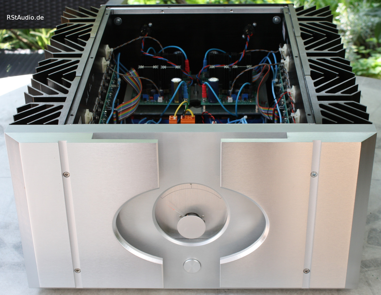
This board contains the input circuitry with the selectable voltage gain (24dB or 30dB) and the bypassable AC coupling, the UGS5 module and the two bias circuits for the bridge output stage.

You can see the 4 trimmers with which the output stage is adjusted. The two trimmers in the middle influence the absolute offset of the two outputs to ground and the differential offset of both outputs to each other. The two outer trimmers adjust the quiescent current of the two parts of the bridge output stage.
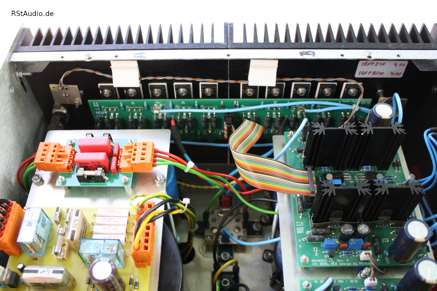
Output Board
06-08-2021
The output board with its 20 power MOSFETs is mounted directly on the heat sink. You can see the two parts of the bridge output stage – 10 MOSFETs each – on the structure of the PCB. The power resistors to the left and right of the board belong to the circuitry for the single ended class A operation of the output stage. On the left of the heat sink there is also a thermo switch that shuts down the output stage as soon as the temperature of the heat sink exceeds 75°C.
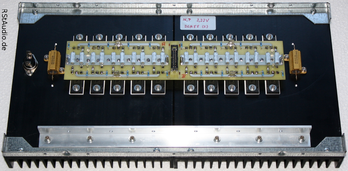
In the final configuration, I did not use the simple circuit with the resistors. A somewhat more complex circuit, as found in the newer power amplifiers from Pass Labs, is used.
This technique can be used for all push-pull amplifiers. A very nice introduction can be found in the book
Audio Power Amplifier Design Handbook – 5th ed.
Douglas Self
Focal Press
ISBN: 978-0-240-52162-6
in chapter 11 Class-XDTM: Crossover Displacement Technology.
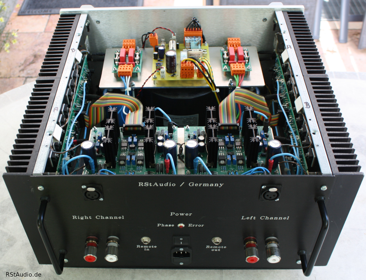
Power Supply
06-08-2021
The power supply determines the audiophile quality of the unit, especially with power amplifiers. With the exception of the transformer, I decided to use a dual-mono construction for this amplifier. This means that each channel has its own power supply. The transformer is only present once, but has separate windings for the channels.
As usual with all my units, I have connected a DC filter in the primary supply line of the transformer. I describe in detail how to design such a filter in Tips & Tricks. Here I use 4× 22000µF/25V electrolytic capacitors as I have them available in larger quantities.
The construction of the power supply units per channel is classic. Behind the fused secondary windings of the transformer, a snubber network is installed that strongly dampens the oscillating circuit – secondary winding of the transformer and junction capacitances of the diodes in the bridge rectifier. Behind this network follows a discrete bridge rectifier with Ultra Fast Soft Recovery diodes from International Rectifier (HFA25PB60). Connected to this is an electrolytic capacitor bank with a capacity of 4× 47000µF and 2× 0.22Ω/25W for CRC filtering. I can only use the CRC topology here because I’m sure that I won’t leave the class A range of the power amplifier with my loudspeakers – in B mode you would get a modulation of the music signal at the resistors.
Inrush Current Limiter and Remote On/Off
06-08-2021
From approx. 400VA, toroidal transformers have such high inrush currents that a normal house fuse usually blows. For this reason, it is necessary to limit these so-called inrush currents. The board shown here is also used in the Aleph J and in the Hypex power amplifier. The circuit has proven itself to me over the years.
In addition to the current limiter, there are two circuit components on the board that switch the power amplifier on and off with a remote DC voltage and provide for the delayed switching of another device.
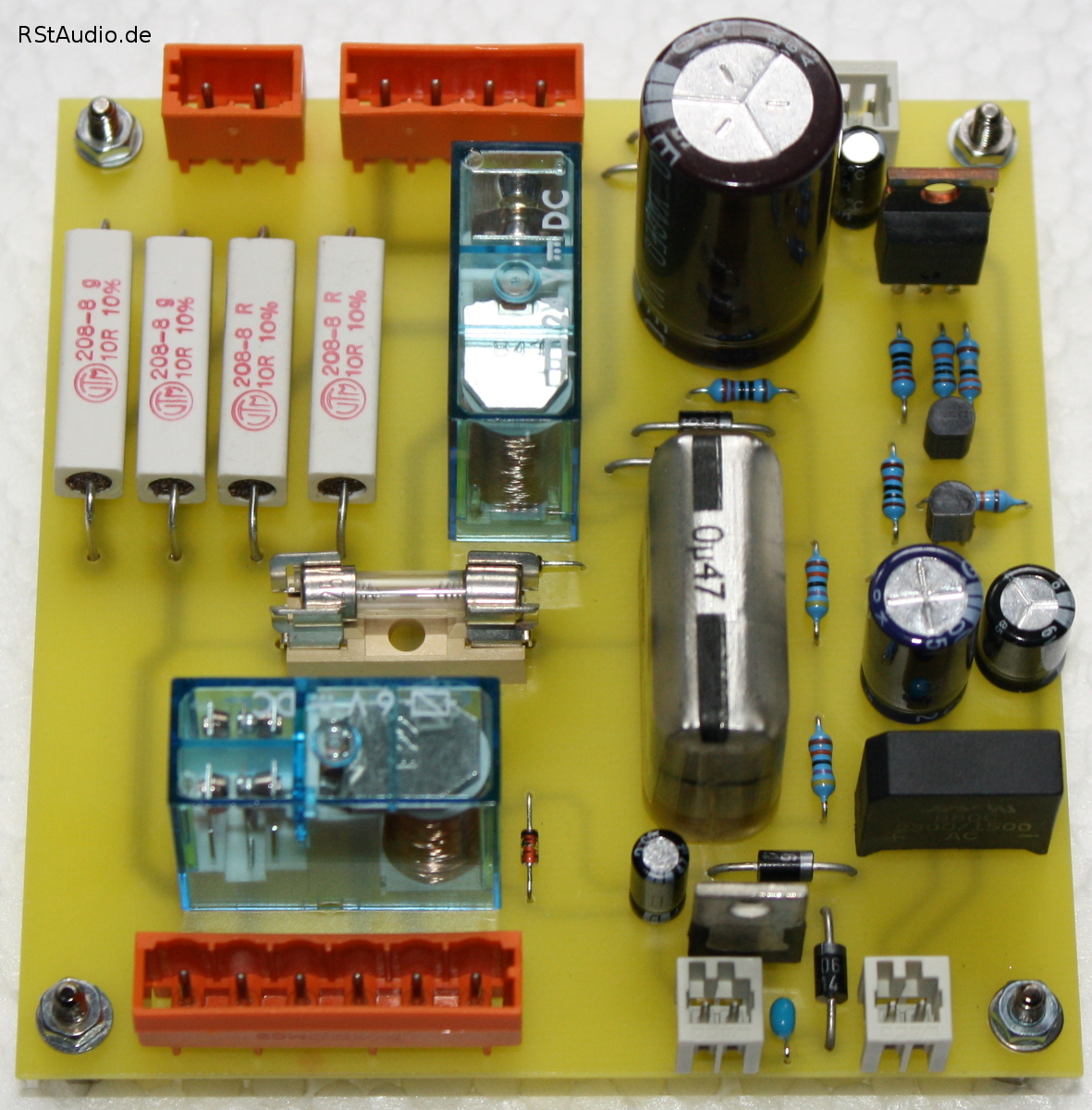
The wiring diagrams for this board can be found in the description of the Hypex Class D power amplifier.
First Start-Up
06-08-2021
The first commissioning – still without a back panel – took place on 23-03-2014. The first impressions were rather sobering and in comparison with the Aleph J, the XA30.5 performed worse. Four days later, however, the first “aha” effects appeared and another two days later it was clear where the journey was heading. The XA30.5 needs some break-in time.
In the meantime, I would rate the comparison with the Aleph J like the comparison between the X0.2 and XP-30 preamplifiers. I have listened to music with great satisfaction with the Aleph J for several years and it is without doubt an outstanding power amplifier. But if you compare it directly with the XA30.5 – and at the moment I only have one stereo power amplifier on the system, i.e. the 2 Quads per channel run in parallel on one channel of the XA30.5 – it becomes abundantly clear which power amplifier should be given priority. As with the preamplifiers, the XA30.5 is characterised by its resolution and richness of detail – simply indescribable and, for me, beyond words.
Once again, I am amazed at the progress that is still possible.

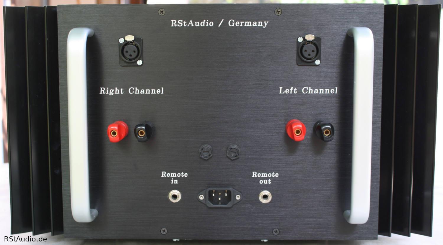
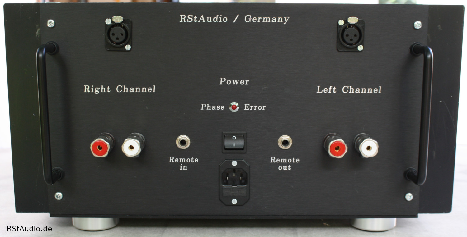
The picture below shows the rear panel of the ES4 with the inputs and outputs.
Changes to the Original Design
06-08-2021
Of course, I have made a few changes to the original circuit diagrams of the XA30.5, as I always do with my replicas. I have plans from 2007 and so I refer here to the design of the XA.5 series at that time.
The biggest changes I made have been to the power supply unit. Actually, the power supply is completely designed by me and I only looked at the circuit diagrams of the XA.5 series for the most important data – output voltage and current.
- In the original design there is only one power supply for both channels, with me it is a dual-mono design starting from the secondary side of the transformer (see above).
- The total capacitance in the original power supply is 180,000µF, with me it is 376,000µF.
- The passive power supplies are equipped with CRC filter stages, in the original they are only capacitors – reasons see above.
- On the primary side I used a 230V/AC DC filter.
- As inrush current limiter for the transformer I don’t use a simple NTC, but a small sequence control which switches off the current limiting element completely (no unnecessary heat source).
- On all secondary side voltages I used a snubber network. This prevents a high frequency resonance from forming on the DC voltages.
- There is a circuit part that switches the power amplifier on and off remotely.
I have also made changes to the audio circuits.
- The AC input coupling can be bypassed.
- The operating point of the two JFET differential amplifiers in the UGS5 module has been optimised.
- I use a Hawksford cascode in the UGS5. This again reduces distortion.
- At the output of the UGS5 I use Toshiba MOSFET’s as in the newer designs from Pass Labs.
- For the Single Ended Class A output power I do not use the simple resistor circuit.
- The Single Ended Class A output power was increased by me compared to the original by a multiple.
Rebuilding to a XA30.8
06-08-2021
In mid-2016, I converted both power amplifiers to the XA30.8. To do this, I had to redesign both audio circuit boards – with the bigger changes being made to the front end.
Surprisingly, the audiophile performance has once again improved considerably. Even if the difference between the XA30.5 and the XA30.8 is not as great as the comparison between the XA30.5 and the Aleph J. It always amazes me how (small) changes to the design can further improve the audiophile performance of a device.
For my friend Guido, I built a power amplifier in an enclosure from Chinese production, which was modelled on the X.5 series. The enclosure itself weighs around 20 kg, making this power amplifier very unwieldy in terms of its dimensions and, above all, its weight. However, it is a feast for the eyes and I always enjoy the design – as long as I don’t have to move it.