!!! Printed Circuit Boards available !!!
Table of Contents
Introduction
10-02-2020
An electrostatic loudspeaker consists of two stators and a swinging foil which is mechanically clamped between the stators. For this simple principle to work, the foil must be conductive and biased with an electrical voltage. The stators are then driven in antiphase by the music signal and the foil begins to swing in time with the music. Unfortunately, this does not work at low voltages, the foil must have enough space to move to transmit a noticeable loudness and air is a good insulator.
Consequently, the Quad ESL 57 applies approx. 1500V/DC (high frequency) and approx. 6000V/DC (bass) to the foils. Also the music signal needs much higher amplitudes than normal power amplifiers provide, so this signal is transformed by a transducer.
A mains transformer with connected voltage cascades in Greinacher circuitry is used to generate the high voltages required for the foils. The lower high voltage of the tweeter is tapped after the first cascade.
Over the years, the diodes in the Greinacher circuit become “tired” and the DC voltages on the foils decrease noticeably. The deflections of the foils decrease. Therefore it is absolutely necessary to replace at least the diodes in the cascade during a revision of the Quads. I have done something like this at the Renovation of my Quads 2011.
At the Refurbishment of my Quads 2020 I decided to build up and install a completely new EHT unit.
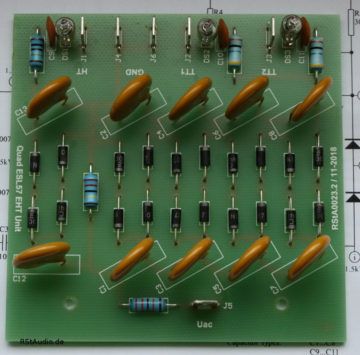
Description of the Circuitry
04-06-2021
The aim of the development was to avoid casting the cascade with wax as in the original and to ensure functional safety despite this. In addition, I did not want to tap the tweeter’s high voltage from the bass cascade; instead, the tweeter got its own cascade. At the output of the cascades there are also networks of resistor, capacitor and neon lamp separately for each individual foil.
These things are not new and have been described elsewhere for quite some time, but I think they are very good ideas and so I wanted to include them in my implementation of the Quad EHT Unit.
The output network should go back to Anders Enquist. Unfortunately I didn’t find a direct link to it, but I found a description of the network’s advantages in my huge documentation on Quads collected over the years:
The idea of it is that the neon lamp isolates the panel from the EHT supply until there is a voltage across the capacitor which is high enough to flash the neon lamp. This takes some 20 volts or so. When the lamp flashes a fraction of a second the panel is charged. Apart from improving the sound, it’s a health inspection as well. If everything is going well you should notice a short flash from the lamp now and then. If it flashes all the time there is a short circuit. If, on the other hand, it doesn’t flash at all, there is a component break down in which case the panel connected will be dead. Soundwise, this tweak will make the bass leaner but with better impact. Sounstage depth will increase too.
… This bring a considerably tighter bass. You may feel the mid-range opens too, but I believe that it is a subjective side-effect of better bass definition. …
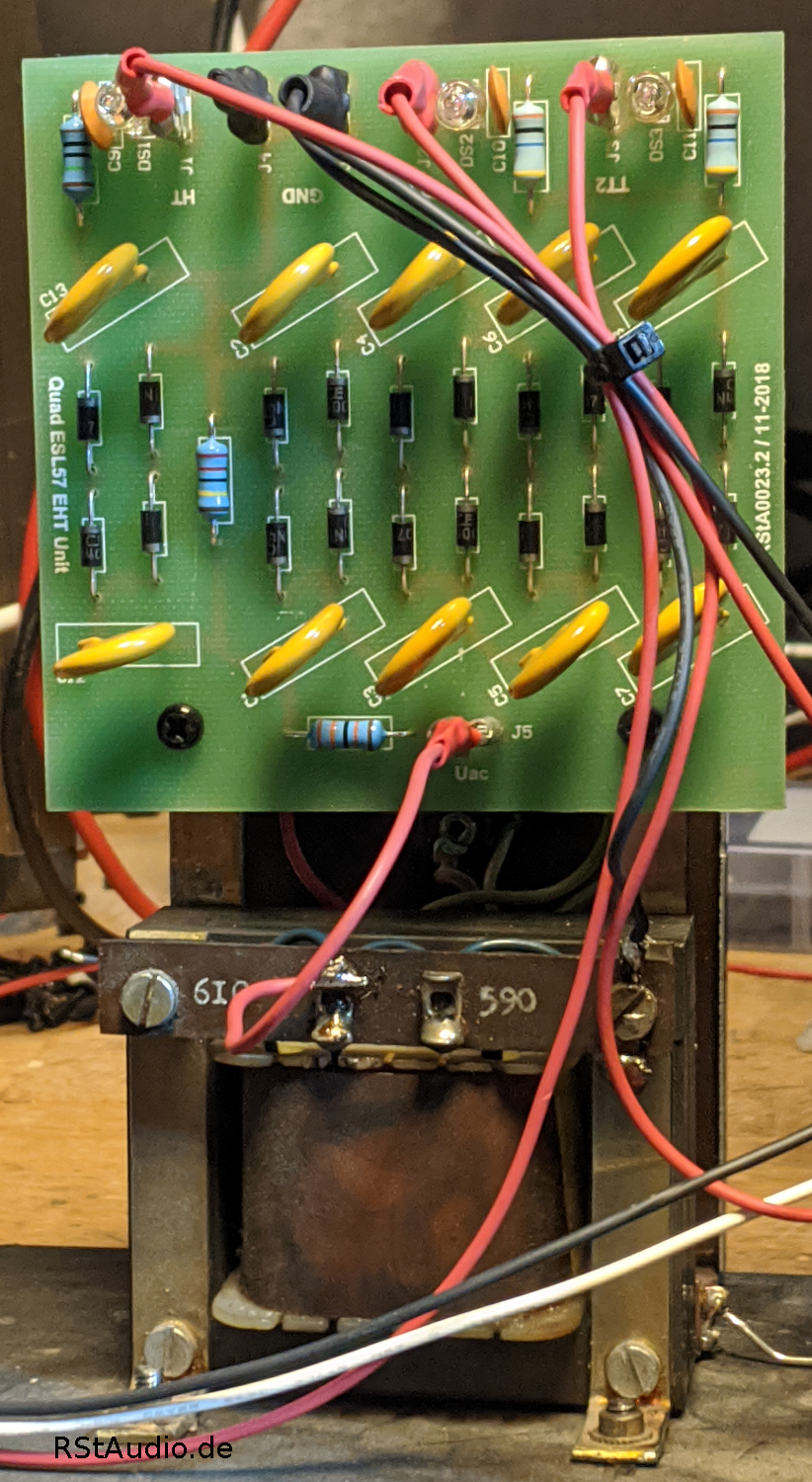
As you can see in the picture above the EHT Unit is still connected to the 610V/AC winding of the transformer. For better adaptation to the existing voltage situation all my Quads are now connected to the 590V/AC tap. Together with an upstream RStAudio Quad ESL Voltage Regenerator this results in stable and optimal voltages at the foils.
My requirements for the PCB, however, also have their price, the original size cannot be achieved with it and, as a consequence, my PCB has to be fixed in a different way. We decided to screw the board to the mounting strips that are attached to the transformer. To do this, we have to drill 2 holes and mount the PCB with insulating spacers. I had reservations at first because the fastening via only 2 points seemed too weak to me, but practice has shown that this is sufficient.
Printed Circuit Board
30-03-2024
I had some requests for the circuit board and so I decided to have a small series made. If you are interested, please contact me using the contact form below.
Please ensure that the e-mail address is correct. Otherwise, answers to the request are simply not deliverable. You can assume that I will reply to every request.
Unfortunately, the contact form does not work for some users. In this case, please send me an e-mail to
info[at]rstaudio[dot]de
Please replace the information in the rectangular brackets accordingly (SPAM protection).