
!!! Don’t Ask for Schematics !!!
As long as Nelson Pass / Wayne Coburn don’t publish this schematics, I also won’t gave it away. The difference between the X0 and the X0.2, is not so big (as NP mentioned) and therefore I don’t want to compromise the commercial success of this wonderful preamplifier.
Table of Contents
Introduction
2007/07/17
In the year 2006 I had contact with another very enthusiastic DIY audio designer. After an intensive change of informations he send me a copy of the Pass X0 service manual. Mainly I want to learn something about the technique behind the volume switching with bipolar transistors. But of course you can imagine what follows – after studying the schematics I started with the design of my next preamplifier (VV4) around a X0 clone, including a lot of ideas from my Aleph P preamplifier. My Pass XOno clone should also be a part of this concept. The result is the following design
- Audio Unit
- Pass X0 preamplifier clone with an electronical volume regulation
- 6 inputs, including a tape monitor, switched with relays
- muting relays at the output
- active regulation of the power supply
- stand by mode
- external digital control board
- digital I²C bus communication with the controller
- unregulated DC power supply from the Control Unit
- Phono Unit
- Pass XOno Clone Phono MC/MM preamplifier clone
- unregulated DC power supply from the Control Unit
- Control Unit
- operation of the preamplifier with a μC / concept of the Aleph P
- digital I²C bus communication with the Audio Unit
- unregulated DC power supply for the Audio and Phono Unit
- Power Unit
the VV4 had replaced my VV3 / Aleph P clone since 2008/04/19
Audio Unit
2008/05/23
At this place I have to thank first of all Mr. S. from H+S Leiterplatten Service.
Without him I was unable at that time to produce such a big PCB.
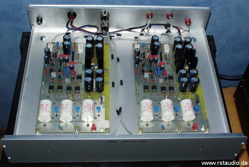
The main part of the audio unit is a clone of the PassLabs X0 preamplifier.
All used FET’s and MOSFET’s are matched. The input circuit is a copy from my Aleph P. In the regulation of the audio power supply I used once again (see my Ono clone) not the 7815/7915 combination of the original design. You find in my design the, in my opinion, better regulators LM317/LM337. Most of the electrolytic capacitors are the FC types from Panasonic. The resistors in the audio path are nonmagnetic types from Dale. – unfortunately bigger types than I have expected.
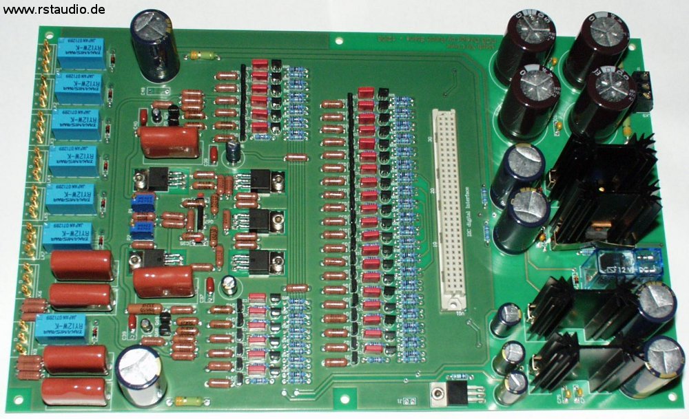
VV4 Audio Unit – Pass X0 Clone
What I don’t like in the original design of the X0 is the direct connection of the digital and analog parts of the preamplifier. The bipolar transistors of the volume control are switched directly out of the digital system. As a result the analog and digital grounds must be connected. In my design I used an I²C bus for the communication to the control circuit of the volume control bipolar transistors. With this serial bus I have the possibility to separate the two grounds very easily. The I²C bus signals are statically when there are no changes of the volume and therefore there is also no influence of the digital signal in the audio system during a normal operation.
With the schematic you clearly see how I have realized the electrical isolation between the microcontroller and the audio electronic. With PF1 all signals of the I²C-Bus and all needed voltages attained the I/O driver board. With IC1 and IC2 the relays are swithed – here we need no isolation, the relays are doing it by nature. IC4 do the electrical isolated coupling of the I²C-Bus from the microcontroller to the audio electronic. With IC3, IC5, IC6 and IC7 the bipolar transitors of the volume control are switched. They get their voltage from the analog power supply of the X0 board. As long as nothing is switched all digital signals are staticaly and therefore there is no influence from clock signals into the analog section during normal operation. VG1 is used for an electrical and mechanical connection of the I/O board to the X0 audio board. With the jumpers JP1 and JP2 the I²C-Bus addresses are set for the left and right channel.
With IC8 I have implemented a chip to measure the inner temperature of the case. This circuit is only used on one of the two I/O Control Boards (address conflict of the I²C-Bus). I think that after a relative short time of operation the inner temperature of the Audio Unit is stable and with IC8 I can measure it during normal operation – there is an extra menue point within the software of the Control Unit.
- Schematic of the I²C-Bus Control Board
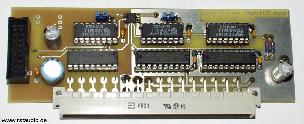
VV4 Audio Unit – I²C-Bus Control Board (old Version)
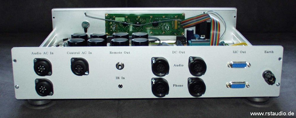
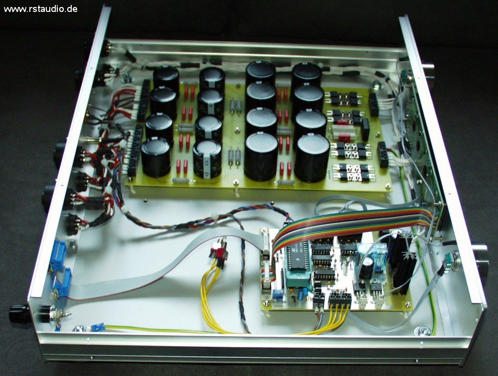
Following you find two photos of the open audio unit. Easy to recognize are both external digital I/O boards. The internal cabling of the audio signals are made with van den Hul D101.
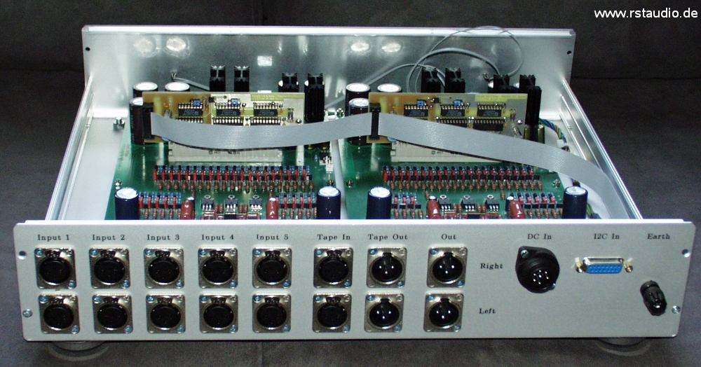
View into the VV4 Audio Unit from Behind
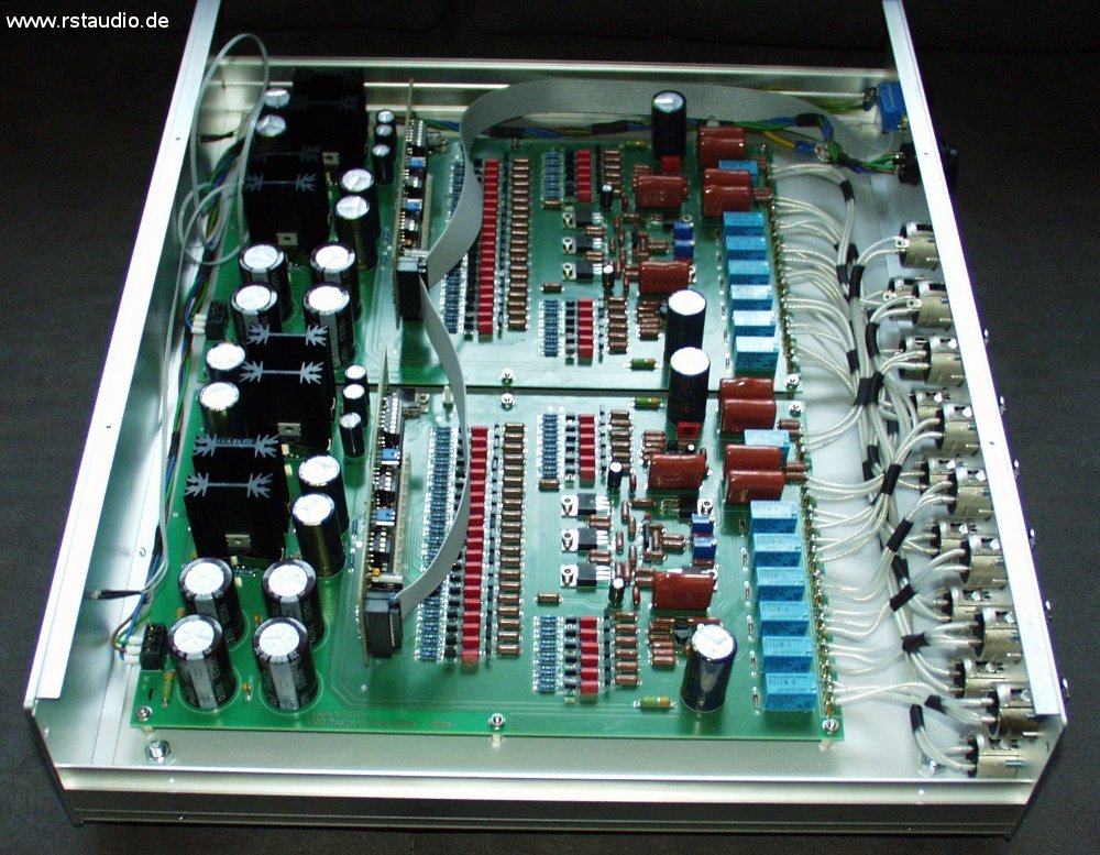
View into the VV4 Audio Unit from one Side
Phono Unit
2007/08/19
The phono unit is my Pass Xono clone. I have the same case in use like the once of the audio unit and therefore both units have the same view. The unregulated power supply for the phono unit is coming from the control unit.
All other informations about this part of the VV4 preamplifier you get at my Pass Xono clone side.
Pass XOno Clone Rev. 2
Control Unit
2003/05/23
The Control Unit consists of the following parts
- μC board to control and operate the preamplifier
- LC-Display and Rotation Encoder as a User-Interface
- passive power supply for the Phono and Audio Unit
The μC board based on the board of my Aleph P Clone. The software is able to work with both preamplifiers and uses mostly the same code. The selection of the preamplifiers is made with jumper JP3.
- Schematic of the Controllers
- Schematic of the Encoder Inputs
- Schematic of the Power Supply
I use the for me well tried Atmel AT89C51RC2 (IC1) microcontroller. All parameters from the user are stored in the I²C-Bus EEPROM IC2. The encoder signals and both (normaly not used) pushbuttons are routed trough debouncing circuits (RC low pass and inverter) to the μC. The volume encoder gives an interrupt during a falling or rising edge. A too fast change of the volume is avoid with IC9. Q2 and Q3 is used for a remote signal to switch on and off external equipment (e.g. power amplifiers).
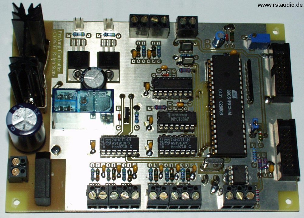
VV4 Control Unit – μC Board
The software has its bases at the code of the Aleph P clone. I have it revised and parts of the software, which I never used to operate the Aleph P, I have taken away. The concept of the operation had proved one’s worth – particularly the interrupt controlled volume setting – and therefore I had completely taken over it.
The passive power supply consists of discrete bridge rectifiers with HFA08TB60 (Ultrafast, Soft Recovery Diode) and a combination of electrolytic capacitors and resistors. The complete capacity of both channels has about 134000μF. The power supply is certainly strong channel separated (dual mono). The ground of both channels are connected via 4.7Ω/5W resistors with earth to avoid ground loops.
- Schematic of the passive Power Supply
- Schematic of the Capacity per Channel
- Top Overlay of the Board
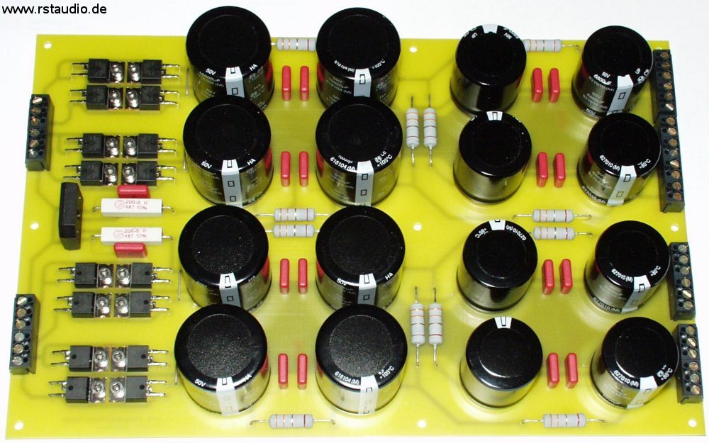
VV4 Control Unit – passive Power Supply
The next photos showing the Control Unit with the complete wiring in the open case. The two wonderful knobs are once again made in excellent quality from Enrico V. (see Aleph P). Therefore I send at this place
Sincere Thanks to Enrico V.
for his wonderful work.
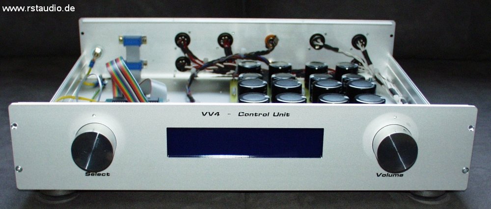
VV4 Control Unit Front View
VV4 Control Unit from behind
VV4 Control Unit from one side
You can see that the development of the software wasn’t finished – the controller sits on top of a Textool socket and the two pushbuttons (yellow cabling) I used to debug the software. They are not part of the finished system.
Power Unit
2003/05/23
The main parts of the Power Unit are the needed transformers for the preamplifier. You find here the complete 230V/AC wiring. Also included is a DC filter and a phase detection. This time I used a more complex 2 stage 1A line filter from Schaffner.
- Schematic of the DC-Filter incl. the transformer for the control electronic
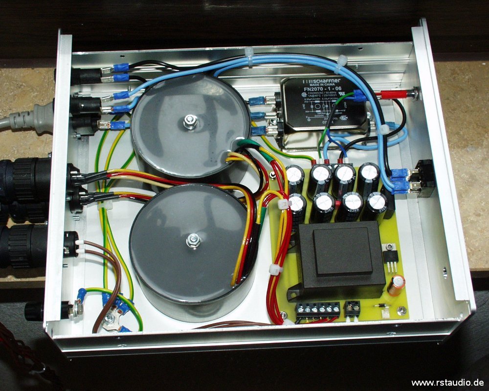
VV4 Power Unit von the Top