Table of Contents
- Introduction
- Circuit Description
- Commissioning of the Prototypes
- Assembly of the Aleph J
- Rebuild 2022
Introduction
09-08-2021
I use four Quad ESL 57 as speakers. They are a very difficult load to drive and it is not easy to find an adequate power amplifier for these speakers. One of the main requirements for a suitable power amplifier is short-circuit resistance. It is especially difficult because I use two speakers per channel and connect them in parallel. A power amplifier based on a current source concept like the Zen or the Aleph’s are of course ideally suited here and so I have been driving the speakers very successfully with the small Zen’s for a number of years. However, these lack a bit of power and so I wanted to realise a similar concept with more output power.
Having used the Zen power amplifier for many years, I naturally followed the further development around the DIY homepage of Nelson Pass. After carefully following a discussion about rebuilding an Aleph J in the AAA forum, where the first positive results were reported back, I decided to build a pair of these power amplifiers in mono design in mid-2010.
I would like to say at this point that the design of this power amplifier is mainly based on the following patent by Nelson Pass, which describes the Aleph power source.
- Amplifier Having an Active Current Source
Nelson S. Pass
US 5710522, Jan. 20, 1998
Circuit Description
09-08-2021
The Aleph J follows the circuit design of the Aleph series. It is also a two-stage concept with a p-channel JFET differential amplifier with current source in the input and a single-ended Class A output stage based on the concept of the Active Current Source with two output stages connected in parallel.
Nelson Pass itself describes the amplifier in the related user manual as follows:
…
Meanwhile, it’s been about 13 years since I designed the Aleph 3, and I have such affection for that series that I revisited the design.
…
The Aleph J has about 15dB less negative feedback than the original and achieves comparable distortion, bandwidth and damping figures. It also has about 15dB less noise. Those of you with delicate tube preamps will be happy to see a 242kΩ input impedance with vanishing capacitance.
I consider it the best of the Aleph series.
The Aleph J carries on in the tradition of the Pass Labs Aleph series, combining those elements that were particularly right about the Aleph 3 and 30, and re-thinking those areas open to improvement. Unlike its First Watt predecessors the F1 and F2, the Aleph J is a voltage source amplifier – a regular sort of amplifier like the ones you already know and love.
There are differences between the Aleph J and its predecessors:
- Improved power supply filtration with about 20dB less voltage ripple
- Reduced gain on the active current source, giving better overall performance into 8-16 ohm loads
- Input stage using high quality matched JFETs
- Much higher input impedance and vanishing capacitance
- 15dB less negative feedback
- Even greater stability, operating without lag compensation
- 15dB less noise
- No electrolytic capacitor in the signal path
Some things have remained the same – the Aleph J has the same basic 2-stage topology and uses output MOSFETs operating in single-ended Class A mode. It’s distortion is still 2nd harmonic, and it’s sound is still natural and liquid. It is still very reliable. I don’t know of a load that can
damage it.
…
The published technical data for the amplifier are:
| measured at 120V AC with an 8Ω load | |
|---|---|
| Input Impedance | 242 kΩ (RCA input) |
| Damping Factor | 20 |
| Output Power | 25W with 1% THD at 1kHz 30W clipping |
| Gain | 19.6dB |
| Input for 25W output | 1.5V |
| Maximum output voltage | ±21V |
| Maximum output current | ±2.5A |
| Noise | 100µV unweighted, 20Hz-20kHz |
I have made a few minor changes compared to the original. The current source of the input differential amplifier is now adjustable, and the value of the two current sources at the output can be varied. Both give me the possibility to influence the power amplifier’s operating point. Especially important is the setting of the current at the input differential amplifier, whose value has a direct effect on the offset voltage at the loudspeaker output.
For the source power resistors and the output resistors I used 2 1Ω/2W resistors in parallel. For the coupling capacitor in the negative input I use the same 10µF film capacitors from Panasonic as in my X0 replica. The coupling capacitor in the feedback of the Aleph Current Source consists of a 220µF Panasonic FC electrolytic capacitor and a 47nF film capacitor from Panasonic connected in parallel (same type as above).
Since Nelson Pass has not published the circuit for this amplifier, I will refrain from doing so at this point. However, interested parties will certainly find it on the Forum of the AAA or on diyAudio or can contact me by e-mail.
Commissioning of the Prototypes
09-08-2021
I built the first Aleph J power amplifier on a heat sink from HI-FI 2000 (300mm × 210mm × 40mm) with a stated 0.2K/W – but measured it is more like 0.3K/W. The operating voltage was provided by 2 controllable power supplies from the automation technology. Both adjustment resistors (see above) were set to the values of the corresponding resistors of the original circuit.
I didn’t have to change anything on the trimmer for the output current sources – the current was pretty much exactly 1.15A per current source, with a voltage of about 570mV across the source resistors. The deviation between the individual MOSFETs was less than 10mV, which speaks for very well matched transistors – I bought them at ebay. By the way, I simply soldered the source resistors into the circuit unmeasured from the packaging.
I had to adjust the current of the current source of the input differential amplifier. After the output stage was at its working temperature, I was able to adjust the offset to about 0.7mV. However, a longer experiment with the offset voltage at the loudspeaker output is still pending. However, this value has been restored every time I switched on after warming up the circuit.
With an Aleph J alone, I can already say that the replacement of the Zen power amplifiers will bring my system a good step forward. The differences are really serious and I am waiting impatiently for the missing material so that I can finally put two power amplifiers into operation.
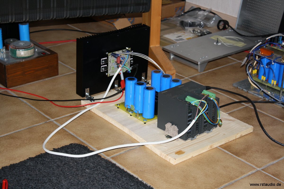
In the meantime, both power amplifiers are running as prototypes. Both power supplies already correspond as far as possible to the finally planned unregulated ones with CRC filtering – 4× 47000µF and 2× 0,2Ω. The toroidal transformers are custom-made in the usual good quality by RONDO toroidal transformers from Müller Elektrotechnik GmbH.
As described above, I have left the trimmers for the output current sources at the value of the original resistor. However, I measured the influence on one output stage and came to the conclusion that an adjustable resistor is completely unnecessary at this point. Consequently, I replaced the trimmer on both output stages with a resistor.
Regarding the sound characteristics, I can only say that my expectations have been more than fulfilled. The Aleph J is far superior to the Zen and brings out details that I have never heard on my LPs / CDs.
The Aleph J is a very big step forward for my system !!!
Assembly of the Aleph J
09-08-2021
My tests with the prototypes have shown that it is worthwhile to drive each speaker of my Stacked Quads individually with an Aleph J. This requires a total of four power amplifiers and so I decided to build two stereo power amplifiers – one per channel.
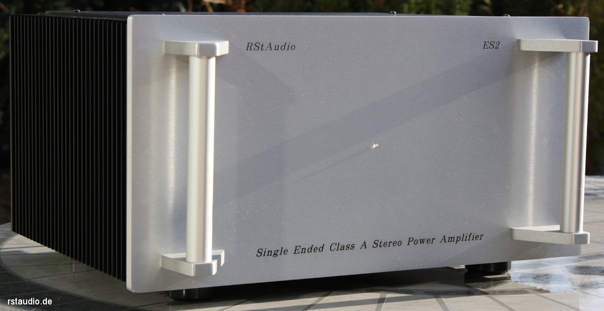
The basis for these power amplifiers are Pesante Dissipante 5U enclosures from HI-FI 2000 with two of the above mentioned heat sinks (order no. 1NPDA05300B). It is made entirely of aluminium with a silver 10mm thick front panel, a bottom panel without and a top panel with ventilation slots.

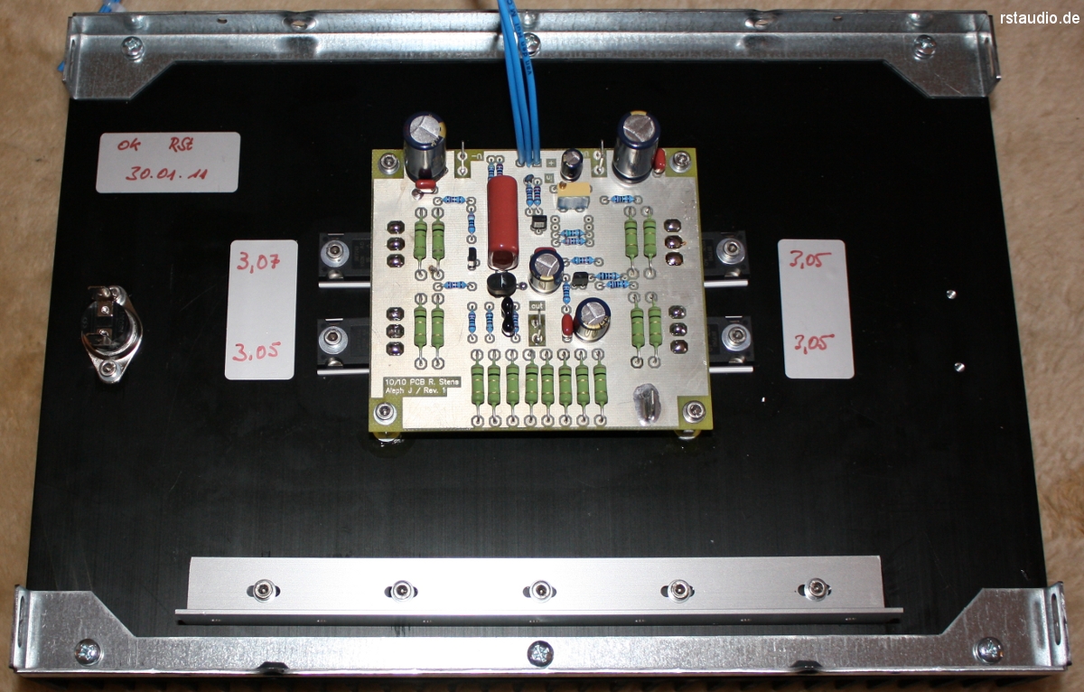
Since I no longer had enough 2SJ109BL for four power amplifier modules, I redesigned the PCB and used two matched 2SJ74BL in the input differential amplifier. In addition, the unnecessary adjustment of the output current sources has been dropped (see above). I also widened the tracks for the operating voltages and the output.
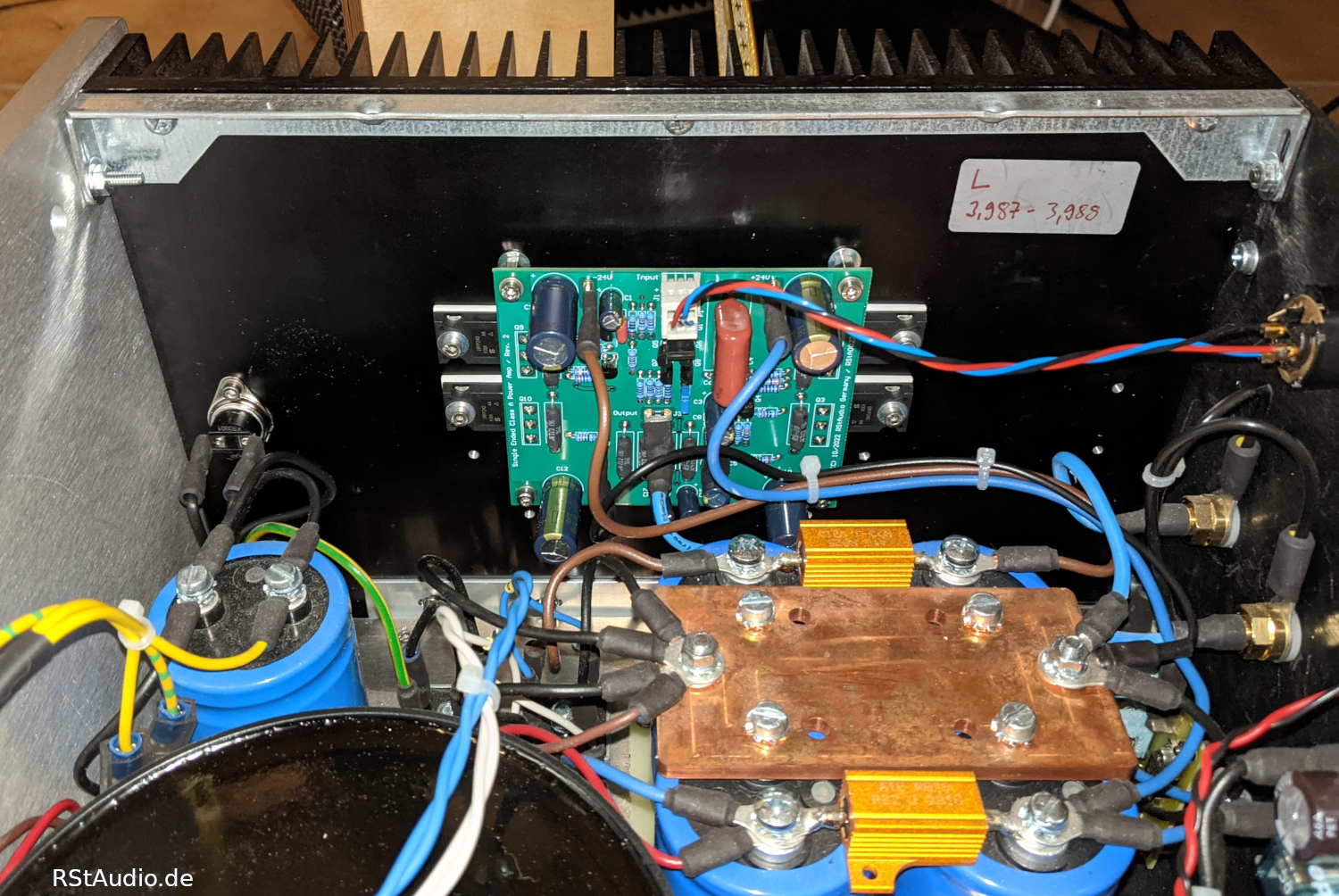
Each Aleph J module is again mounted on a heat sink. This means that the four power MOSFETs can be soldered directly into the circuit board and the signal paths are very short. A thermo switch monitors the temperature and interrupts the 230V/AC supply line as soon as 75°C is exceeded. Furthermore, I have mounted an aluminium mounting bracket on both heat sinks to which the mounting plate for the power supply unit is attached.
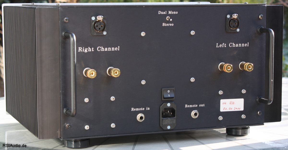
In order to use one stereo power amplifier per channel, the input signal of one channel must be routed to both power amplifier modules. The input impedance of the Aleph J is very high (see above), so there are no problems with parallel connection. However, I wanted to keep the stereo power amplifiers flexible enough to be able to use them for a 2-channel application. For this reason, there is a switch on the back with which both inputs can be switched separately (stereo) or in parallel (dual mono).
I have also connected a muting device to the outputs of both amplifiers. With this circuit, the outputs are short-circuited when they are switched on and off in order to prevent unpleasant noises. The basis for the muting device is a corresponding part of the original XOno circuit.
These power amplifiers are also switched on and off remotely from the preamplifier in my system, for which I need a remote circuit. In addition, the transformers with their approx. 400VA are just at the limit to trigger the house fuse by the inrush current. Therefore, I use the same remote circuit with rush current limitation in the Aleph J as in my Hypex power amplifier.

My prototypes behave absolutely quietly (of course only without signal), so I have decided not to regulate the operating voltage. For the two stereo power amplifiers I use a toroidal transformer for both channels (400VA / 4× 19.5V/5A). This deviates from my basic philosophy of a double-mono set-up, but it saves space in the cabinet and when using one stereo power amplifier per channel, I again have the separation of the power supplies per channel that I favour. I use 2× 22000µF/25V electrolytic capacitors and a bridge rectifier as DC filters in the 230V/AC supply line of the transformer.
After the common transformer, the operating voltage supplies for both channels of the power amplifier are of proven double-mono design. Per channel there are 2 rectifiers and a CRC filtering with 4× 47000µF/40V electrolytic capacitors and 2× 0.22Ω/25W resistors. The two grounds (left / right channel) are each connected to earth via a bridge rectifier.

Finally, a picture of the power amplifier from the rear. You can see the two inputs (XLR sockets) and the speaker outputs on both sides of the rear panel assigned to the respective channels. At the top centre is the stereo/mono switch and below that the mains switch and the mains socket with integrated fuse. To the left and right are the input and output for the remote signal (6.3 mm mono jack).
Rebuild 2022
24-12-2022
Since May 2022, I have been using one of my two Aleph J stereo power amps for the tweeters of my RQM Loudspeaker System. Even though the XA30.8 are the better power amps, the Aleph J does a really good job driving the Air Motion Transformers. In addition, the fascination with the Aleph J’s Single Ended Class A technology has never left me.
Unfortunately, my two power amplifiers now have the unpleasant property sporadically with clearly audible noise to draw attention. I am sure that it is due to a temperature effect, but sadly my attempts to turn this off have not led to success. I therefore decided in October 2022 to redesign the audio circuit board.
But I didn’t just design a new PCB, I also made some – in my opinion very useful – changes to the circuitry.
- To drive the JFET’s in the “sweet spot” I added cascode transistors to the input stage.
- The reference voltage of the input current source is no longer generated by a simple Zener diode.
- For the current source I use a bipolar transistor in TO-225 package (higher power dissipation).
- Switchable servo controller for a regulated DC voltage-free output.
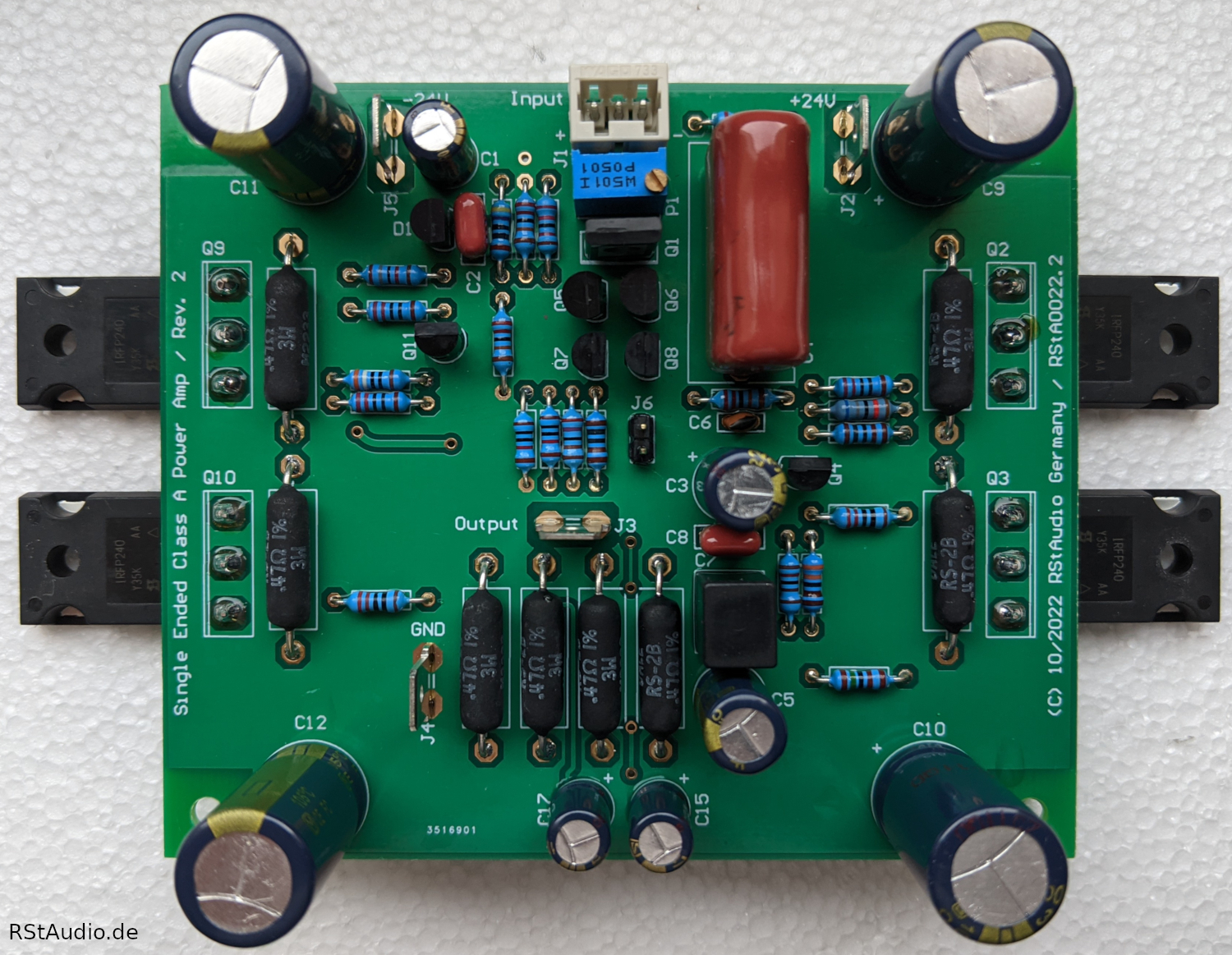
The picture above shows the assembled circuit board of my Aleph J R2. If you look closer you can see four transistors in the TO-92 package below the trimmer. Two of them are the 2SJ74BL and the other two are BC560C bipolar transistors that work as cascodes for the JFET’s. With their help I can operate the JFET’s in their “sweet spot”.
The trimmer is used to set the current of the input current source and ultimately the output offset.
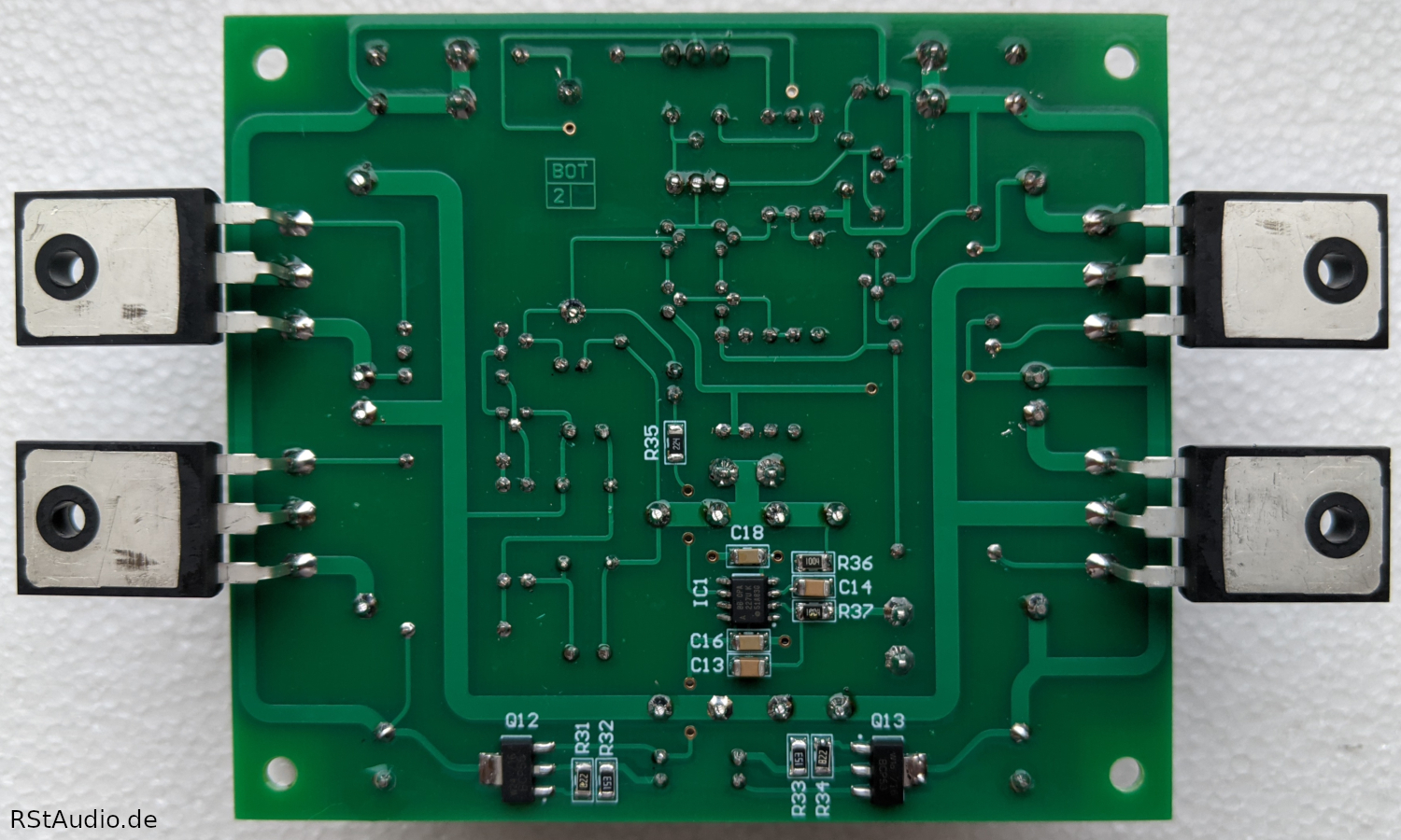
Looking at the solder side of the PCB, the operational amplifier, which works as a servo controller, can be seen. The two transistors reduce the operating voltage of the amplifier to the ±15V required by the OP. The servo controller is only activated by a jumper after the offset at the output of the power amplifier has been optimally adjusted by a manual adjustment of the input current source.
since 22-12-2022 runs the Aleph J R2 in my system