Table of Contents
- Introduction
- Description of the Pass XOno Clone (Rev. 0)
- Power Supply (Rev. 0)
- Prototype
- Rev. 2 – Preamp & Power Supply
- Building the Case
- Setting the Operation Point
- Hints and Changes
- XOno Installations
Introduction
06-12-2021
The excellent results I achieved with the Aleph P replica made me think about a fully balanced audio chain. Since the output level of my preamplifier (transformer and preamplifier by M. Cotter) is very low and I had to set the Aleph P to almost maximum volume and gain to achieve normal listening levels, I decided to also build a Pass XOno. Of course, the positive reports of various rebuild projects and the excellent tests of diverse hi-fi magazines made this decision easy for me. However, it is difficult for me to put my M. Cotter combination into retirement.
Description of the Pass XOno Clone (Rev. 0)
06-12-2021
No significant changes of my own were made to the phono preamplifier circuit. In a discussion on diyAudio the differences between the Ono and XOno design are listed. The member t024484 wrote there on 2005-03-17 :
XONO / ONO
In the very first mail of this thread, KDT asked what the differences are between the ONO and the XONO.
Here it is
- Each channel has now its own set of power supply regulators by means of two times 7815 giving +/- 30Volt instead of one single regulator with MosFets for both channels
- Power Cap’s on the +/- 30Volt lines have been increased from 1000uF to 3300uF//150nF
- C10 has been changed from 10uF into 220uF//47nF
- C1 and C41, both 220uF, have been changed to one single 1000 uF
- on the unregulated side the four 1000uf Cap’s have been replaced by four 10.000uF Cap’s
- C16 330pF, connected to Q14, has been deleted
That’s it
These changes have been integrated into the circuits described here.
I have replaced the 2SC1844 and the 2SA991 of the original circuit diagram with BC550C and BC560C. The circuit diagram covers two sheets (A4 and A3) and shows the moving coil amplifier stage and the moving magnet amplifier including the balanced output stage.
- Schematic of the Moving Coil Preamplifier
- Schematic of the Moving Magnet Preamplifier with Output Driver
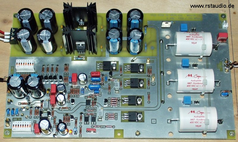
Based on the results with the WIMA MKP4 coupling capacitors in my Aleph P replica, I also used corresponding types for C7, C9 and C38 (10μF/160V) here. The double FET Q5 used is a BL type (2SK389BL). The four 2SK170GR FETs at the input of the MC stage (Q10…Q13) must be selected. Information about this can be found in the threads 13981, 10326 and 60297. For the 220μF coupling capacitors (C10, C19 and C37) I used 35V Panasonic FC types. In parallel with these electrolytic capacitors are 47nF polypropylene capacitors. All resistors are 1% metal filmers and were added to the circuit unselected. In the network for RIAA equalisation I use 1% mica capacitors (C4 and C5) and a measured polypropylene capacitor (C6).
At the input of the moving magnet amplifier, in addition to the switchable capacitors and resistors, there is a pluggable capacitor Cx and a likewise pluggable resistor Rx. I used the pins of an 8-pin IC precision socket as plug-in sockets.
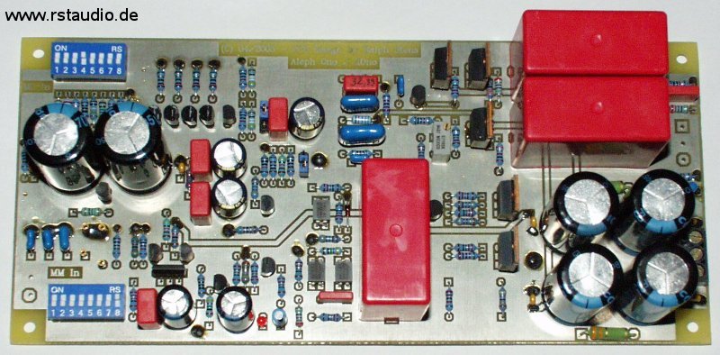
The photo shows one channel of my Pass XOno preamplifier.
Power Supply (Rev. 0)
06-12-2021
Even though I don’t have schematics of the Pass XOno’s power supply, the discussion on diyAudio actually makes it pretty clear what the power supply should look like. Deviating from the regulation used in the Pass Ono with a MOSFET, integrated fixed voltage regulators of the 7815/7915 type are used. These are set to a higher output voltage with a voltage divider. In the design described here I use – in my opinion better – variable voltage regulators LM317/LM337. These regulators should always have a load current of at least 30mA (here forced by R2 and R3) to work in their optimal control range (see TNT-Audio).
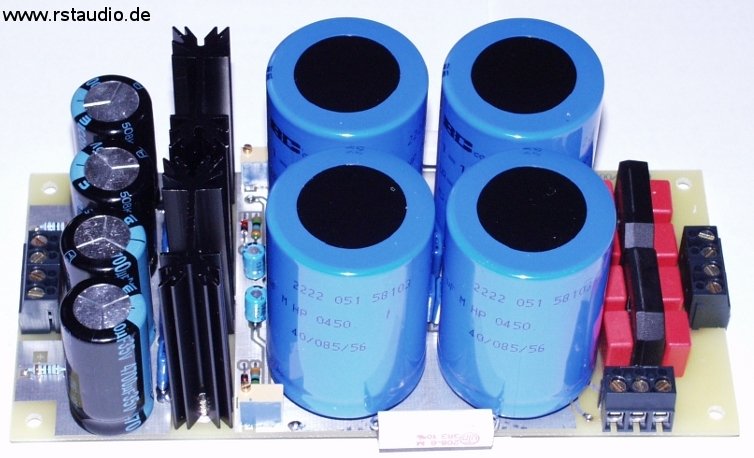
I use a separate bridge rectifier for both voltages (positive and negative) in the symmetrical power supply and thus obtain two full-wave rectifiers. The 10000μF capacitors in both operating voltage branches are connected together in a CRC combination and thus clearly eliminate the remaining AC component of the two voltages at this point. The output terminal has two ground outputs. The second is intended for coupling the ground to the system’s earth (via anti-parallel connected diodes – again a bridge rectifier – and a 5.6Ω/5W resistor). The voltage at the first electrolytic capacitors can be tapped off at an additional luster terminal, which can be used to supply LEDs and the muting relay.
- Schematic of the Power Supplies
Prototype
06-12-2021
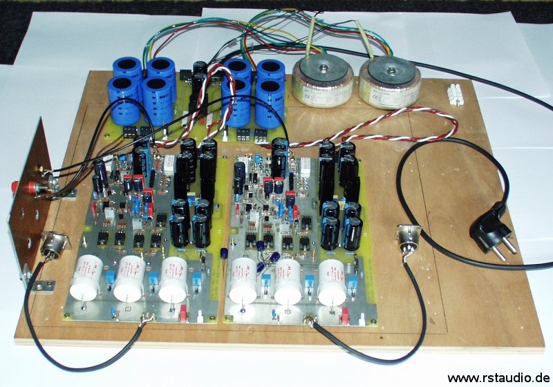
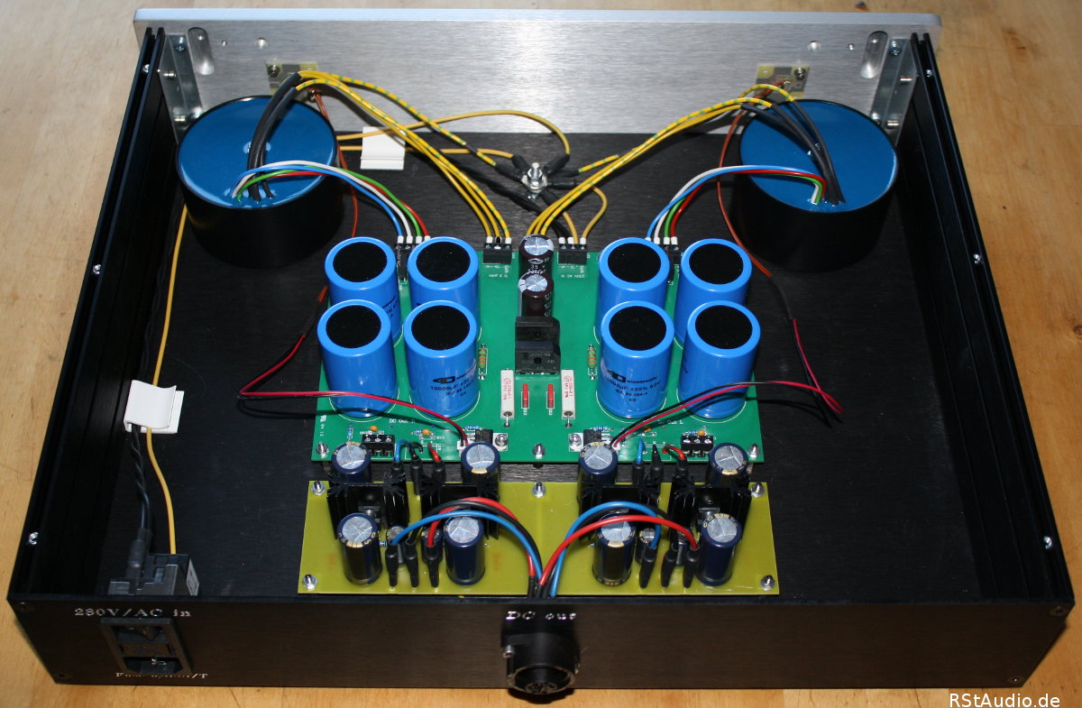
As usual, I built the prototype as a breadboard circuit. For the first commissioning, only the two Pass XOno boards, two power supplies and two standard toroidal transformers (2×30V, 50VA) were used. On the right you can see the two toroidal transformers and the power supplies. On the left you can see the two XOno boards. The audio inputs are at the back and are wired with RG174 to the two cinch sockets. In front are the XLR output sockets.
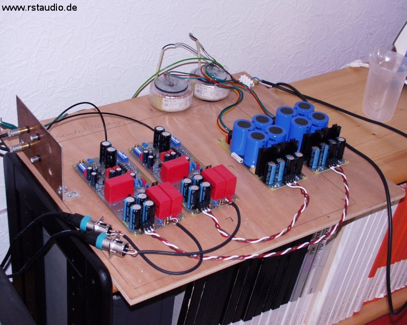
Subsequently, the two audio grounds were connected to earth (via a bridge rectifier, two anti-parallel diodes per channel and two 5.6Ω/5W resistors).
At the time, I operated the XOno with a Thorens TD126 MKIII / SME Series III / Benz Micro ACE L. Since I used the Benz newly with the commissioning of the XOno (I had involuntarily destroyed my old Denon), I cannot make any statement about the XOno alone. However, the chain is really impressive and I hear all my records (more than 250 of them, mainly jazz) as if for the first time. In my opinion, building the XOno is definitely worthwhile and is certainly an asset in almost any audio chain.
In addition to the audiophile properties, the XOno’s low noise is also really remarkable. I operate the Benz ACE L with an input impedance of 499Ω and a -4dB lower gain (JP1 plugged in) in the MC stage. If you don’t have a record on, there is almost absolute silence, even with the volume control on the Aleph P turned all the way up.
Rev. 2 – Preamp & Power Supply
06-12-2021
After the successful commissioning, I made minor changes to the layout – in a revision 1. During the whole time I was living with the prototype, I had been thinking about the layout of the electronics and finally came to the conclusion to do a major redesign and to build an enclosure for this layout. I made the following changes:
- Place larger output capacitors on the audio board
- Route the regulation of the power supply directly to the audio board
- Split the power supply into the rectification with filtering and the regulation
- Rectification, DC filtering and grounding of both channels on one board
Since I plan to place the power supply unit at a somewhat greater distance from the audio cabinet, I was not comfortable with the idea of supplying the regulated operating voltages via the somewhat longer external cable connection required for this. With the division of the electronics in Rev. 2, there are only the unregulated DC voltages, but no AC voltages.
I did not make any other changes to the audio circuit. As mentioned above, part of the power supply (LM317/337 voltage regulator with input and output capacitors) has been added to the board. Also, additional space for the three 10μF coupling capacitors has been created on the board, various capacitors can now be used. These 3 capacitors have also been given additional small parallel capacitors – I have had very good experiences with the use of 100nF Vishay MKP1837. I have also placed 3 test points on the board – the ground can be tapped at TP1 and between TP2 and TP3 the current voltage at resistor R28 (setpoint: UR28 = 0.35V) can be measured.
- Schematic of the Moving Coil Input Stage
- Schematic of the Moving Magnet Preamplifier incl. Output Stage
In the end, I used inexpensive Mundorf capacitors – I was just curious if I could hear a difference to the Wima’s. However, I didn’t want to invest too much money at first. Furthermore, I selected the bipolar transistors Q1 and Q2.
The power supply unit has basically not changed. The CRC filtering of 10000μF capacitors and 3.3Ω resistors has remained. However, the bridge rectifiers have been replaced by four HFA08TB60 (Ultrafast, Soft Recovery Diodes). Both channels with connection of the grounds to earth, as well as DC filtering of the mains voltage, are now on one board.
- Schematic of the complete Power Supply
- Schematic of the Unregulated Power Supply for one Channel

During the operation of the prototype, it turned out that a stable operating point of the circuit is reached only after more than 45 minutes (see also the article about the XOno in LP Magazine 03/2006 page 18). For this reason, I always leave the XOno connected to the mains and a muting circuit for noise suppression when switching on the operating voltage is therefore superfluous. Consequently, there is no short-circuit relay at the output in my XOno preamplifier.
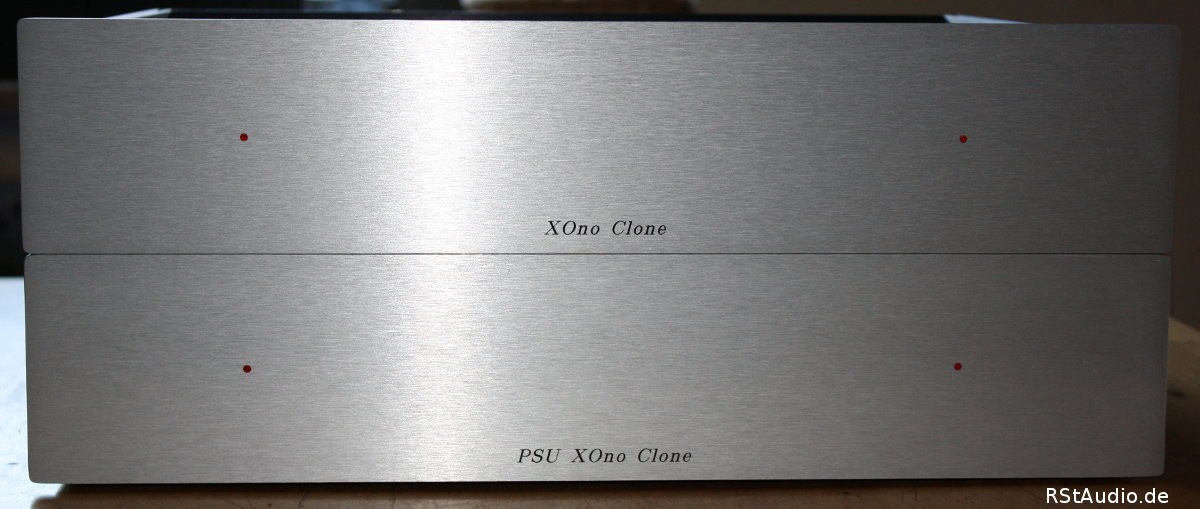
Building the Case
06-12-2021
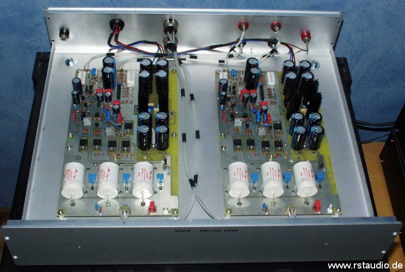
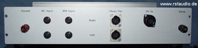
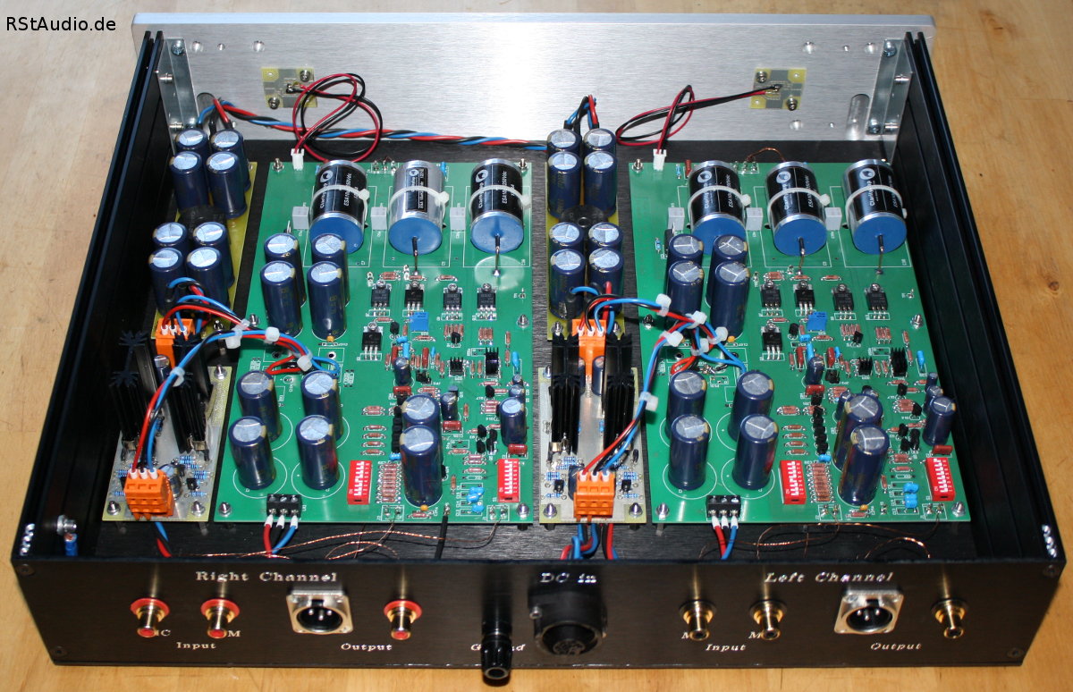
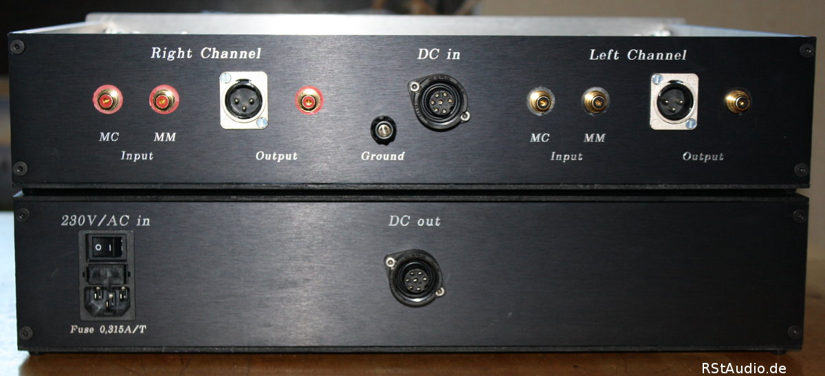
I installed the two audio boards in the ALG 36-44-30 cabinet from Thel Audio-World. The front and rear of this cabinet were milled and labelled at Schaeffer AG. The Van den Hul D101 single cable is used for the internal wiring of the audio signals. For the MC input I used the WBT 0210 AG Nextgen and for the MM input the WBT 0210 CU Nextgen. At the output, of course, there are again XLR sockets from Neutrik. The DC supply is fed via a 7-pin industrial plug from Hirschmann.
In the meantime (the prototype has been around for more than 1½ years) I have started designing my VV4 preamplifier, the XOno has become part of its concept and the enclosure is adapted to this preamplifier – this means that the unregulated operating voltage supply is now fed from the supply of the VV4 Control Unit.
Setting the Operation Point
06-12-2021
To achieve an approximately correct operating point, I calibrated the electronics directly during the first commissioning. The voltage between the test points TP2 and TP3 is measured and set to 350mV with R25. I then left the electronics to themselves for more than a day. All semiconductors had thus warmed up and all voltages and currents had reached a stable final value. Then I adjusted it again and got a very stable operating point (see below).
The following table lists the relevant operating points of my two XOno boards.
| Arbeitspunkte / Operational Points | |||
|---|---|---|---|
| linker Kanal Left Channel | rechter Kanal Right Channel | Bemerkung Comments |
|
| UR28 | 349.9 mV | 350.2 mV | R25 (OP1) |
| UR45 | 74.7 mV | 77.3 mV | IQ10 = 3.40 mA / 3.51 mA |
| UR46 | 76.5 mV | 79.4 mV | IQ11 = 3.48 mA / 3.61 mA |
| UR47 | 76.0 mV | 81.4 mV | IQ12 = 3.45 mA / 3.70 mA |
| UR48 | 76.9 mV | 80.6 mV | IQ13 = 3.50 mA / 3.66 mA |
Please note that the operating point is strongly dependent on the temperature. A small draft in the room caused by e.g. one’s own body movement can already change it.
DC Coupling:
On my board there are still components for an operating point adjustment – R4a, R59a, JP3, JP4 and JP5. They go back to a discussion on diyaudio.com in which an adjustment was described with which one can do without the coupling capacitors at the output. This does not work, the operating points are simply too dependent on the temperature. If you want to operate the XOno without coupling capacitors, you have to equip it with servo controllers.
Hints and Changes
06-12-2021
In the following you will find a few tips and also a modification for the construction of the XOno. They are the result of the experience and feedback I have gathered over the years.
Replacements for the JFET’s
It is becoming increasingly difficult to find JFETs for the XOno. As a rule, you can only find them on ebay or comparable platforms. But the current situation is not completely hopeless and in the following list you will find replacement types where you do not have to compromise. By the way, a BL type can easily be used for Q15.
| Bauteil Components | Original Original | Ersatz Replacement | Hersteller Manufacturer |
|---|---|---|---|
| Q10…Q13, Q15 | 2SK170GR | 2SK370GR | Toshiba |
| LSK170A | Linear Systems | ||
| Q15 | 2SK170BL | 2SK370BL | Toshiba |
| LSK170B | Linear Systems | ||
| Q5 | 2SK389BL | 2× 2SK170BL | Toshiba |
| 2× 2SK370BL | Toshiba | ||
| 2× LSK170B | Linear Systems | ||
| 2SK2145 | Toshiba | ||
| LSK389B | Linear Systems |
Toshiba has discontinued the production of low-noise JFETs and so it is no longer easy to get the replacement types from Toshiba listed above. However, the chance of getting suitable JFETs increases if you can use a larger variety. Of course, if you replace the double JFETs with single transistors, you have to match them.
I have heard several reports of fake 2SK389BLs and therefore advise against getting them from dubious sources. As a substitute, two matched 2SK170BL can be used. The following picture shows how to insert them into the circuit board.
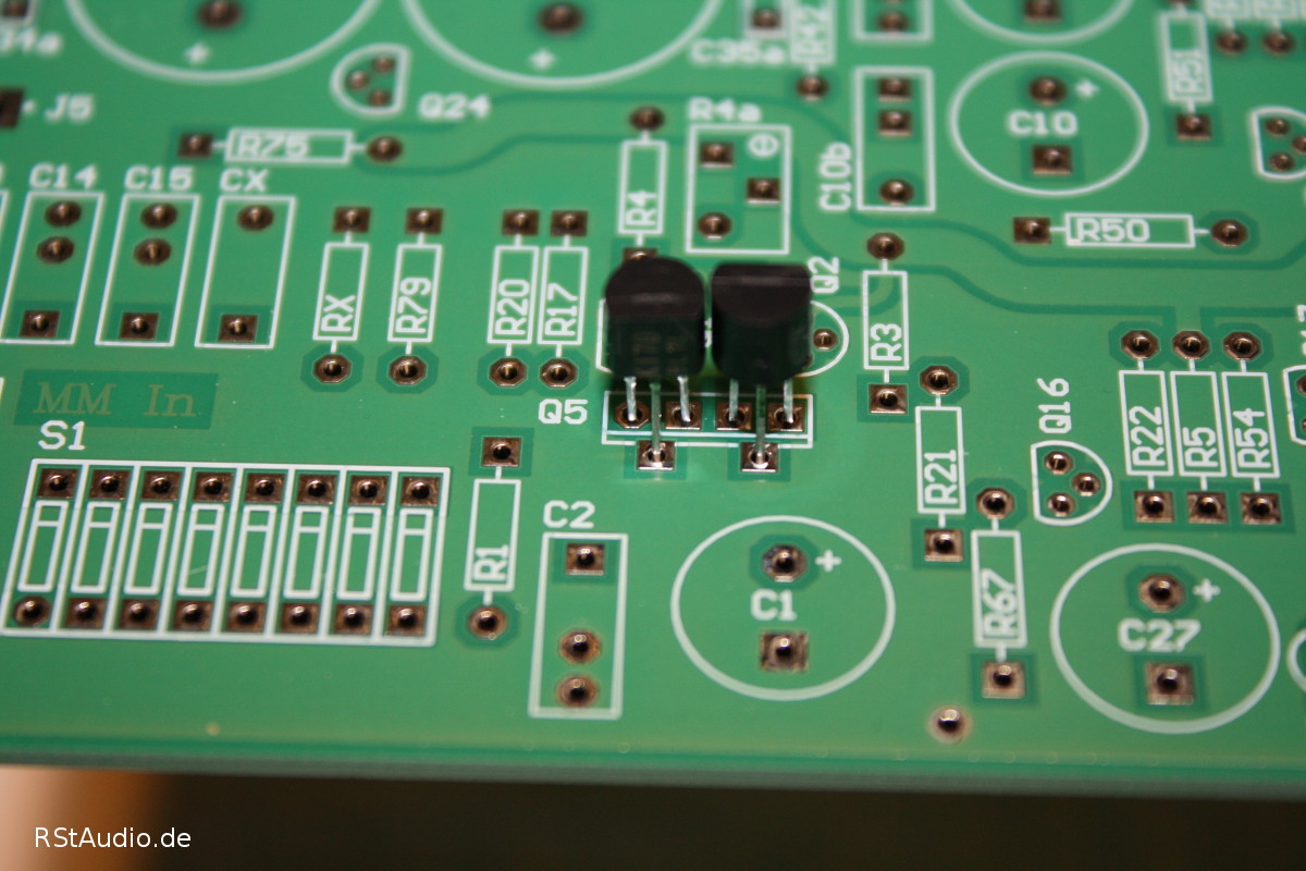
The left JFET has its flat side facing us and the middle pin is bent forward. The flat side of the right JFET is facing away from us. The JFETs are therefore rotated 180° to each other in the circuit board.
D5 LED Reference Voltage
In the thread Help wanted,aleph (cl) ono problem on diyaudio.com I first became aware of a problem with my XOno replica. Shortly after, a DIYer contacted me describing the same problem, and after a few emails between us, he was able to fix it. Here I would like to describe the problem and possible solutions.
The two current sources formed by Q16 and Q17 have the light-emitting diode D5 as a common reference voltage source. This LED receives its operating voltage via the 6.8 kΩ resistor R5. If we calculate the power dissipation of this resistor, the following results
![\[ P_{R5} = \frac{(\mbox{60V}-U_{LED})^2}{\mbox{R5}} = \frac{(\mbox{60V}-\mbox{1,8V})^2}{\mbox{6,8k}\Omega{}}\approx{}500\mbox{mW} \]](https://www.rstaudio.de/wp-content/ql-cache/quicklatex.com-1a39f1d539cd005620028dd6800296a8_l3.png "Rendered by QuickLaTeX.com")
This power loss can be too high depending on the type of resistor used.
There have also been reports of an unstable voltage across the light emitting diode after a certain warm-up time. This also depends on how high the maximum possible current of the diode used may be. The LED current in my replica is ID5≈8mA.
The simplest solution to both problems is to increase the resistance value of R5 to 15kΩ. This reduces the power dissipation of the resistor and at the same time reduces the current through the light emitting diode (ID5≈4mA and PR5≈230mW).
A second possibility is to use the circuit from the Pearl II. Here, R5 is not connected to the positive operating voltage but to earth. The value of the resistor there is 4.75kΩ. This gives an LED current of ID5≈6mA and a power dissipation of PR5≈170mW. However, this solution requires a slight rewiring of the circuit.
The first solution is included in the current parts list and in the circuit diagram above.
Current Sources Q16 and Q17
The circuit diagram shows a voltage of 1V across the resistors R53 and R67 of the two current sources formed by the bipolar transistors Q16 and Q17. This results in a current of I=2.1mA for the current source Q16 and I=6.7mA for that of Q17.
The voltage across the resistors is determined by
![\[ U_R=U_{D5}-U_{BE} \]](https://www.rstaudio.de/wp-content/ql-cache/quicklatex.com-b8021ac946963d1ddce089c28be17351_l3.png "Rendered by QuickLaTeX.com")
If the LED voltage is e.g. 1.8V, the voltage at the resistors will be more than 1V. There are two possibilities to adjust the current sources to the original value:
- Measuring an LED with ULED≈1.6V
- Adaptation of the resistors to the actual LED voltage
I will demonstrate here the way of the second solution for both current sources.
Let’s assume a voltage of 1.2V at the resistors. This calculates the current to IQ16=2.5mA and IQ17=8mA with the original resistors. Especially the deviation of the second current source is considerable. In order to adjust the current to the value specified by Nelson Pass, the resistance values of R53 and R67 must be adjusted.

This shows very well that you do not have to carry out lengthy series measurements on light-emitting diodes and that you can achieve the same goal much faster – and cheaper – by simply measuring the actual voltage and adjusting the resistance values.
Addition:
When I built the XOno PCBs for my VV5 preamplifier, I used light-emitting diodes from Reichelt (order no. LED 3MM ST RT) and initially fitted the resistors R53 and R67 with the standard values. At the first start-up, the voltages across both resistors, measured on both boards, were constant at 1.3V. This results in the following values for the assembly:

If you do not want to connect resistors in parallel, the E96 values R53=200Ω and R67=620Ω are sufficiently accurate.
Adjustment of R25
Before the first start-up, the trimmer R25 should be set to a halfway reasonable value. Otherwise it can happen that the current in the output stage is so high that one of the 33Ω resistors will burn out. In my case a value of
![\[ \mbox{R25}\,||\,\mbox{R25P} = \mbox{800}\Omega \]](https://www.rstaudio.de/wp-content/ql-cache/quicklatex.com-badc28c94fb241a6787bcc6074a074ce_l3.png "Rendered by QuickLaTeX.com")
measured in the circuit has proven to be a good starting value.
LM317/337 Voltage Regulators
I am often asked how to set the voltage regulators IC100 and IC101 before the first commissioning. First of all, a little mathematics as can be found in the data sheets of the two voltage regulators. Since the same statements apply to both regulators, I will only refer to the positive voltage regulator LM317 (IC100) in the following.
The output voltage for IC100 is calculated from
![\[ U_a = U_{ref} \left( 1+\frac{\mbox{P100}}{\mbox{R100}}\right) + I_{Adj}\cdot\mbox{P100} \]](https://www.rstaudio.de/wp-content/ql-cache/quicklatex.com-b861c7f448990e303e126147251b657d_l3.png "Rendered by QuickLaTeX.com")
Since IAdj is very small, the second term can be neglected. The value for Uref = 1.25V can be found in the data sheet. To be on the safe side, the output voltage should be set lower than the desired operating voltage and adjusted to the correct voltage of ±30V during commissioning. For an output voltage of e.g. 25V, the potentiometer P100 must be set to the following value:
![\[ \mbox{P100} = \left(\frac{U_a}{U_{ref}}-1\right)\cdot\mbox{R100}\approx\mbox{5,1k}\Omega \]](https://www.rstaudio.de/wp-content/ql-cache/quicklatex.com-4776b3629045f88763615d9835e6b309_l3.png "Rendered by QuickLaTeX.com")
The same applies to the voltage regulator IC101. If you now set both potentiometers (P100 and P101) to a value of approx. 5kΩ – which simply means middle position with a total value of 10kΩ – you get an output voltage of around ±25V.
MC Input Capacitor
With two of my moving coil pickups I heard a kind of “rattling” – i.e. no hum – in the loudspeaker. With one of them it was so quiet that it was completely covered by the running noise of the record, but with the other pickup it could also be heard in the pauses between two pieces of music. I could adjust the volume of this noise with the amplification factor of the MC input stage, so it must come from the first stage of the MC amplifier.
Since this noise was a periodic oscillation and such a behaviour must have something to do with capacitances and inductances, it was obvious to take a closer look at the input capacitance C29. There is an excellent Phono FAQ by Arlt van den Hul. In it, he describes that an MC pickup does not really need a capacitance, but that capacitances of well over 100nF do not have a negative effect because of the low inductance of the pickup’s coil.
This statement was confirmed by my own experiments. Using a cinch adapter, I switched capacitors in parallel to the 100pF input capacitor – starting with 220pF – and finally fixed a value of 1nF (Wima FKP2). The noise is completely eliminated – so there is no more oscillation – and the MC input in my VV5 preamp is nearly as quiet as a line input with the pickup off. It has also been good for the sound of the pickups, they have become even more open.
Resistors and Coupling Capacitors
Although I built the original XOno in the VV4 with Dale resistors, I would no longer recommend such a setup today. Sound differences are not really audible. I built the complete VV5 with normal metal film resistors. The money saved would be better spent on coupling capacitors. From my own experience I can highly recommend the Obbligato Gold Premium, but they are too big for the board. The Clarity Caps ESA 250V (see below) give excellent results and are my current recommendation as coupling capacitors.
XOno Installations
06-12-2021
Every now and then I not only sell the boards for an XOno but also build a complete phono preamplifier. I would like to show you here what these XOno’s look like.
XOno for H.F.
This XOno has some special features in the power supply. Circuits from my VV5 have been used as additional circuit boards in the construction. Types of HI-FI 2000 are used as housings.
The power supply housing contains the two toroidal transformers and the power supply board. Electrically connected behind the PSU board is an additional circuit board on which capacitance multipliers are mounted.
CLC filters for the DC voltage are built into the voltage input of the actual XOno preamplifier. On the XOno PCB, the circuits around the LM317/337 voltage regulators are replaced by discrete voltage regulators. The coupling capacitors used are 10μF Clarity Caps ESA 250V. You can also see that – at the owner’s request – Dale resistors are used.
The last picture shows the two enclosures from behind with their connections.
Since the capacitance multipliers and discrete voltage regulators are circuits from the current preamplifiers from Pass Labs I will not publish the schematics.