!!! Printed Circuit Board’s Available !!!
Table of Contents
- Introduction
- Description of the XOno Hardware
- Microcontroller Board
- Power Supply
- Installation in a Housing
- Audiophile Review
- FAQ
- Printed Circuit Boards
If you are interested in my first XOno replica, you can find the report under the following link: XOno 2008.
For those in a hurry: Here you can find reviews from the DIYers about the XOno 2019.
Introduction
01-05-2019
Unfortunately the gold dust – the outstanding 2SK170 JFETs from Toshiba – are running out. The supplier I always recommended can’t offer any more. So it becomes difficult to impossible to build an original XOno.
At the end of 2018 I decided to build a MC-prepreamplifier based on the XOno topology with the 2SK2145 JFET’s from Toshiba as a plug-in card for my DPV1 phono preamplifier. It should serve as a test setup for a new XOno to be designed. I put this plug-in card into operation at the beginning of 2019 with great success and thus nothing stood in the way of a redesign of the XOno.
The design should still be as close as possible to the original XOno design, but with a few useful improvements from the design of the Pass Labs XP-15 and my own experience of many years. I have written the following points into my personal specifications:
- Optionally assembled with 2SK170 / LSK170 or 2SK2145.
- Reference voltage source instead of the simple LED for the current sources of the RIAA amplifier.
- Modern design of the inverter (XP-15).
- Optionally assembled with DIP switches or relays.
- Optional AC or DC coupling at the outputs of the RIAA stage and the inverter.
- DC power supply input with CLC filter.
- Discrete power supply regulation with a modified Jung regulator.
- Extension Board with additional Equalization Characteristics (Columbia, Decca, EMI & Teldec)
- Microcontroller PCB for the relay operation.
- Use of mainly through-hole components.
Description of the XOno Hardware
11-08-2020
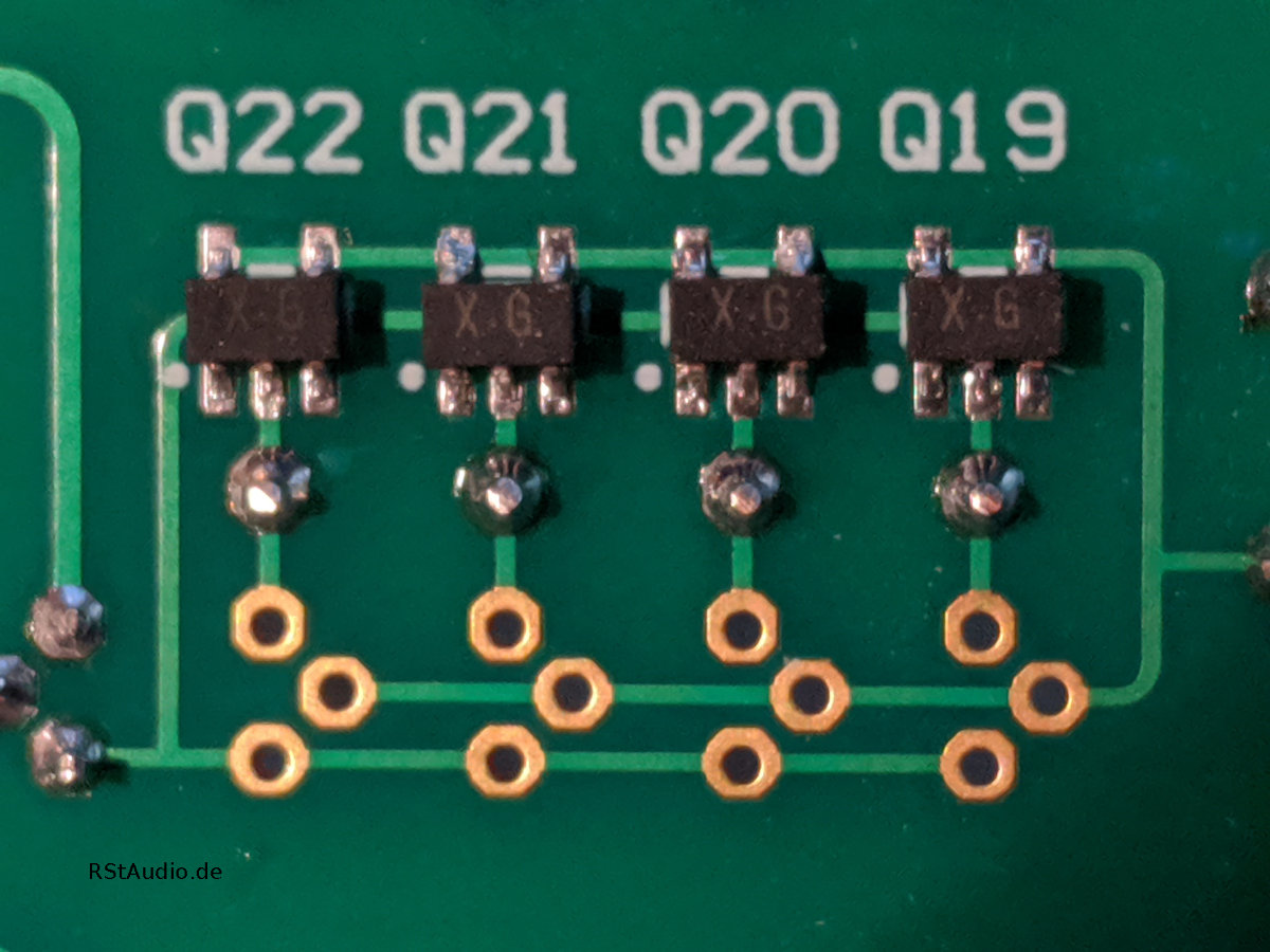
The design goal was to develop a XOno with available components. Therefore you can replace the original 2SK170 (gold dust) with the currently available 2SK2145. The 2SK2145 is a double JFET in a 5 pin SOT case. The design of this phono preamplifier is nearly identical to the original, with some useful changes and improvements from the XP-15 design and my own many years of experience.
MC Input Stage
The circuit topology of the MC stage corresponds to the XOno, only the setting of the gain I have moved to the output of this stage – as in the XP-15 design. This seemed to me to be more practical than changing the amplification factor in the original. Both stages of the MC preamplifier are based on the JFET’s mentioned above. You can build the stage with five 2SK170 or with a corresponding amount of 2SK2145. When using the double JFET’s, this results in a significant reduction of the noise due to the double number of JFET’s connected in parallel. However, the operating points must be adapted to the number of transistors – other resistance values.
At the input of the MC stage there are 8 switchable resistors for the adaptation to the used pickup. In the original XOno these resistors are switched by a DIP switch on the PCB. This can also be realized with this PCB. For those who want it more comfortable, relays can also be soldered to the PCB. In combination with the optional microcontroller board, the resistors can be selected by rotary encoder and display.
The 3 amplification factors of the MC stage are also set either at a DIP switch on the circuit board or with relays via microcontroller.
MM Phono Preamplifier
In this stage you can use either 2SK170BL or 2SK2145BL for the input differential amplifier. Otherwise no adjustments have to be made to other components. There is also a significant improvement in the reference voltage of the current sources compared to the original XOno. I don’t use a red LED anymore but a TL431 reference voltage diode. This means that the operating point is no longer dependent on the lot of a component used. The TL431 has a specified output voltage of 2.5V in the circuit topology used here. Otherwise this amplifier corresponds to the original XOno design.
It is possible to switch 3 capacitors at the input of the MM amplifier. The same applies here: either DIP switches or relays are used in combination with the optional microcontroller board.
Inverter
The inverter is located at the output of the MM stage and is used to generate the inverted signal for a balanced output signal. I decided to take a more modern design of Pass Labs – the IRFD9110 in the original will get extremely hot. The current inverter behaves much more pleasantly here and has at least the same sound level.
Servo Controller
In the original XOno the MM amplifier and the inverter are AC coupled – there are 10μF foil capacitors at the output of both stages and at the input of the inverter. You can build these XOno in this way and stay with the original, the corresponding space for the large foil capacitors is available.
However, there is also the possibility to omit these coupling capacitors if both servo-controllers are mounted. Thus the outputs of the stages are kept electronically DC-free. I used this circuit concept for the first time with great success in my DPV1.
The Voltage Regulator
The original XOno PCB gets its DC voltages from the external power supply which is located in a separate housing. Also in my design such a distribution was and is intended. The unregulated DC voltages are then regulated on the board of the XOno to the required operating voltages. Pass Labs used 15V voltage regulators with raised reference point (7815 & 7915) to regulate the ±30V operating voltage. In my old XOno I used variable voltage regulators (LM317 & LM337).
In the current design I use modified Jung regulators. I have used them for the first time in my DHA and am amazed by the audiophile and control performance of these regulators. I also use a CLC filtering with current compensated chokes and a total capacity of 60000μF on the printed circuit board in front of this regulators.
The EQ Board
Older, interesting classical recordings often do not sound very good with a modern phono preamplifier. This is not due to the quality of the preamplifiers, but solely to the wrong equalization curve. Recordings from the 1960s or older have often not been cut with an RIAA curve (e.g. Deutsche Grammophon).
During the development phase of this XOno the wish for additional equalizer curves was brought to my attention. But since not everyone is interested in it, including me, I chose the way over an add-on board. With this board the XOno is extended by 4 additional characteristic curves (Columbia, Decca, EMI & Teldec). With this it should be possible to equalize most of these recordings correctly.
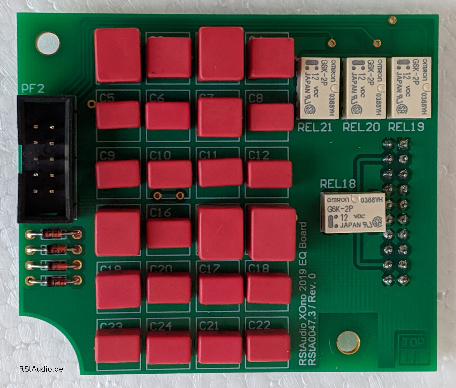
On the photo above you can see the EQ board for one channel. The required resistors are placed on the bottom side of the board (SMD 1206). The capacitors are all measured to achieve the most accurate reproduction curve.
Photo’s of built XOno’s
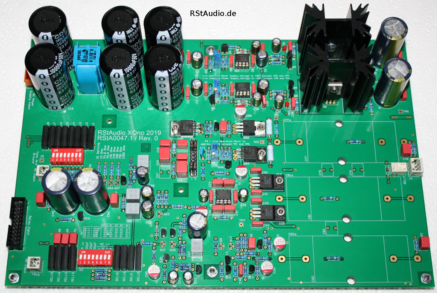
In the picture below you can see a finished XOno. Here it is the variant with the capacitor coupling and without relays – thus finally the classical XOno construction. As coupling capacitors I used types of Aeon, which I still had in stock. Comparable types were also used in the XOno.
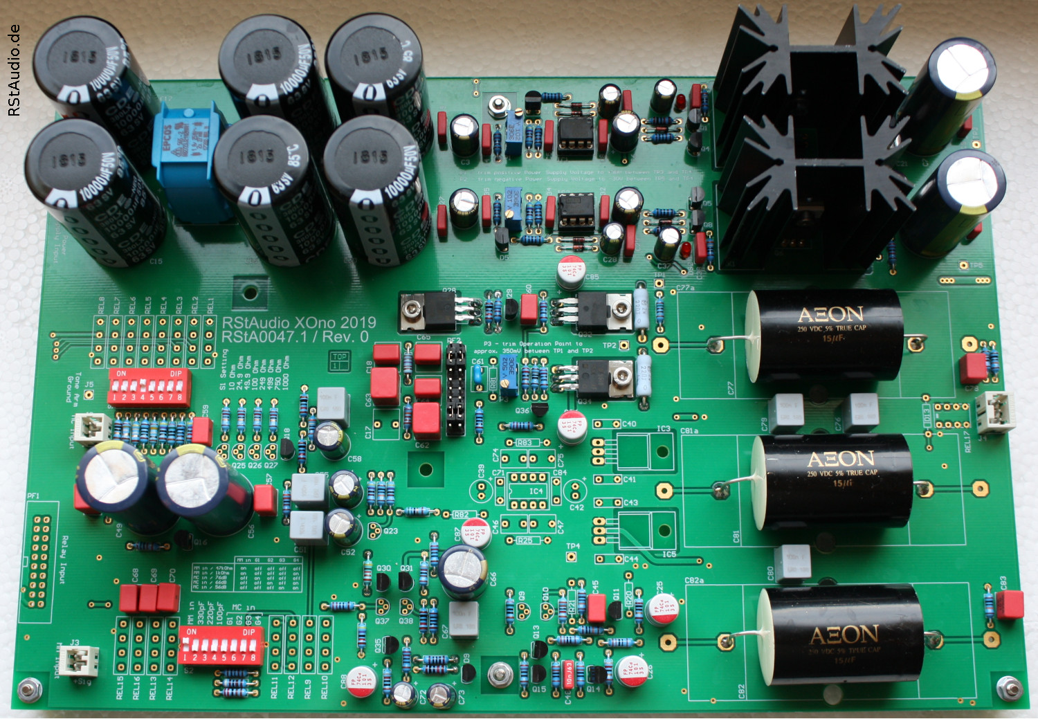
The next picture shows the version with 2SK2145, servo-controller and relay.
Microcontroller Board
10-08-2022
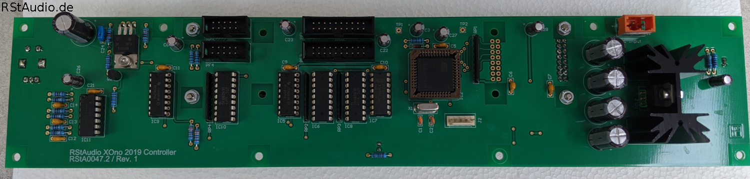
As mentioned above, there is an option to use a microcontroller board to switch the relays – which take over the function of the DIP switches – on the XOno board. A display with 2 rows and 20 columns as well as a rotary encoder are available for operation.
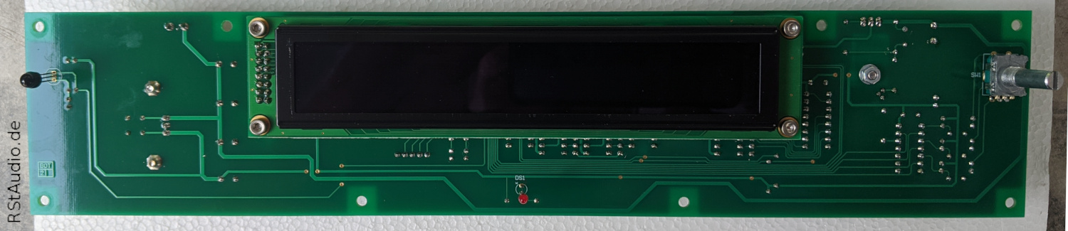
I use an OLED display from Display Visions (formerly Electronic Assembly). You can use 2 types on the board, the EA W202 XLG with 5,5mm and the EA W202 XDLG with 9,66mm high letters. I prefer the bigger display, it is easy to read from a distance. Unfortunately, it is now no longer in production and so you have to be satisfied with the small display.
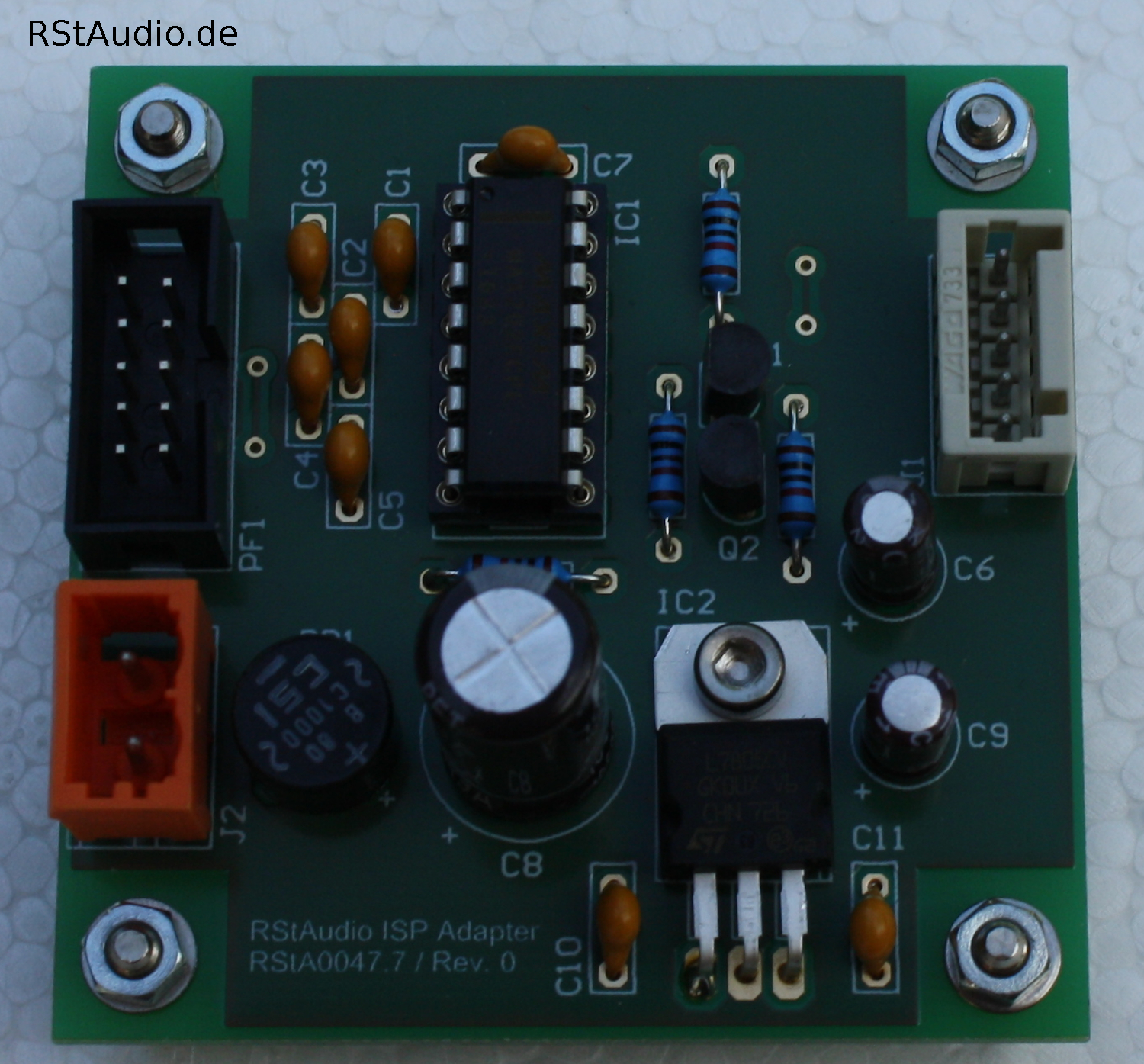
The board uses an AT89C51ED2 from Microchip (formerly Atmel). Of course I deliver a controller board together with a programmed microcontroller. But there is also a connector to which you can attach a programming interface. If you want to write your own software for the XOno, you have the possibility to do so. I only use free software – SDCC and Flip.
The controller board also has an IR receiver built in. The complete operation of the XOno can be done with this remote control.
Power Supply
25-03-2020
An audio preamplifier and of course especially a phono preamplifier depends in a very special way also on the quality of the power supply used. Over the years I have gathered a lot of experience in this field and my circuits have become more and more complex, but also better and better. The RStAudio XOno 2019 got a power supply where I implemented all my knowledge at the time of development. About the last part of the power supply, which is located on the XOno circuit board itself, I have already written above. At this point it deals with the generation of the unregulated DC voltages.
230V/AC DC Filter
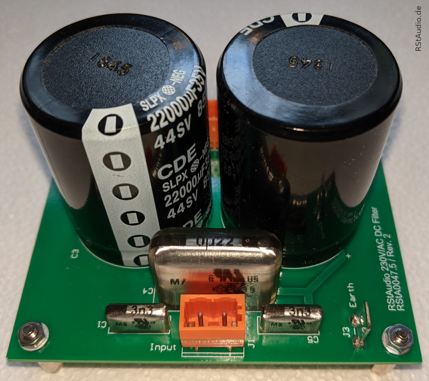
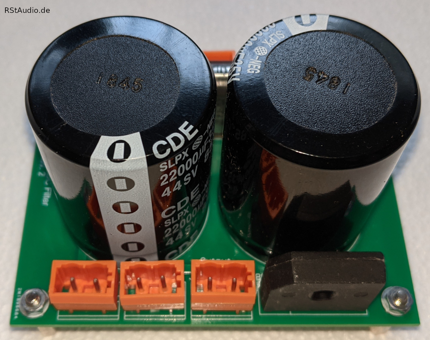
Nowadays there are more and more disturbances on the 230V/AC grid. It is therefore essential that these disturbances do not affect the DC supply of the audio circuits. As a first protection mechanism all my power supplies have a power socket with integrated filter from the company Schurter. Another filter with Wima X2 and Y2 capacitors is following, followed by a DC filter. This filter ensures that any DC voltage components in the 230V/AC supply do not drive the transformer into saturation. There is enough space for larger electrolytic capacitor values – the rule of thumb is that the DC filter needs 10000μF per 100VA.
On the following picture you can see this circuit with the two filters. The circuit board is connected between the mains socket and the primary winding of the transformer. In the pictures below, the PCB is equipped with 2x 22000μF. For the XOno 2019, 2x 10000μF are sufficient at this point.
Unregulated Power Supply for the Audio Circuits
This circuit board is used to generate the unregulated symmetrical DC voltage for an audio channel. As you can see on the photo below it is not only the usual circuit consisting of a rectifier and a capacitor.
With the input – on the photo below left – two secondary windings of the transformer are connected. Directly following this, two snubber networks can be found which strongly dampen the oscillation tendencies of the oscillating circuit of the transformer’s inductance and the junction capacitance of the diodes. The bridge rectifier with discrete Ultra-Fast Soft-Recovery diodes follows. The next part of the circuit then consists of the CLC filtering with 4× 10000μF capacitors and a current compensated double choke. This is followed by a capacitance multiplier which removes any residual AC voltage components (ripple) from the DC voltage. The ground is connected to earth via a diode-resistor network. An extremely good, but not yet regulated, DC voltage is available at the output.
The output voltage is of course dependent on the ratio of the transformer and the AC voltage currently available at the socket (230V/AC ±10%).

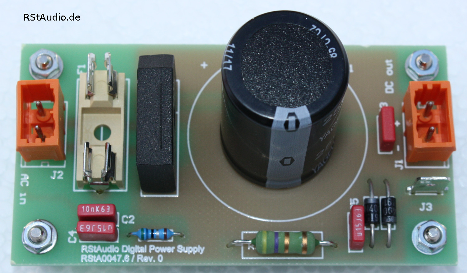
Unregulated Power Supply for the Digital Circuits
The power supply for the digital circuitry, i.e. finally for the controller, is of rather modest design. There is also a snubber network and a ground-earth connection, but otherwise there is only a classic unregulated power supply consisting of a rectifier and charging capacitor. Even if the electrolytic capacitor was chosen here very large. For the controller, which has no direct connection to the audio circuits, this power supply is more than sufficient.
Installation in a Housing
14-08-2023
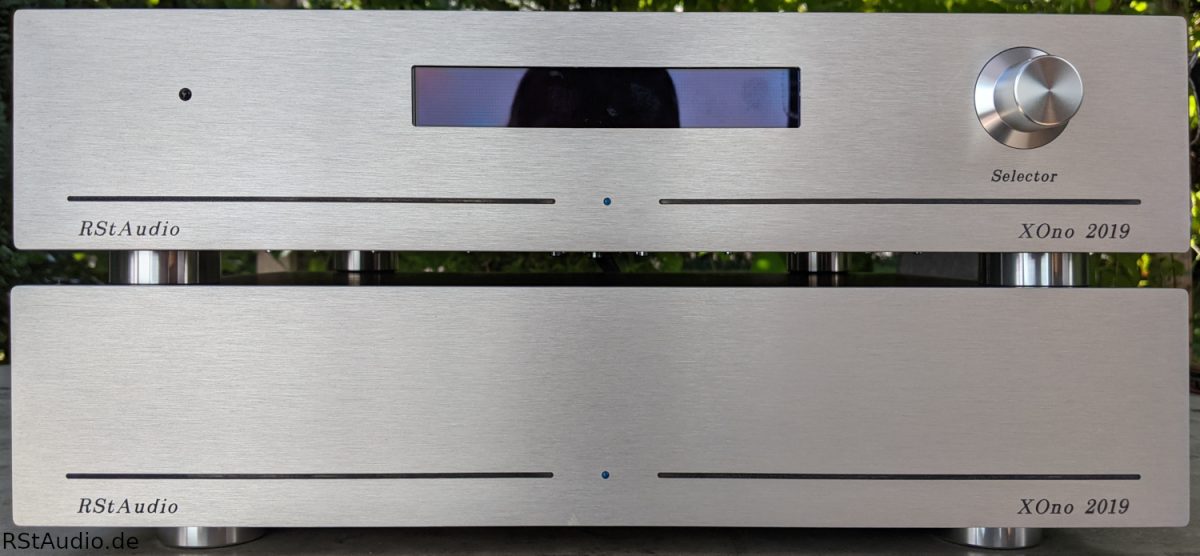
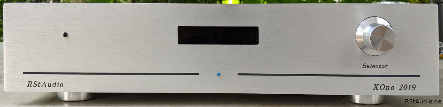
As always, I bought the cabinets in Italy. On the photo at the top of the page you can see the view from the front. The very nice front panel design comes from my friend Guido. Good to see is the display in the middle and below it the LED for the operating voltage. On the right side the encoder is positioned and on the left side you see the IR receiver. The power LED is useful because the display can be switched dark during operation.
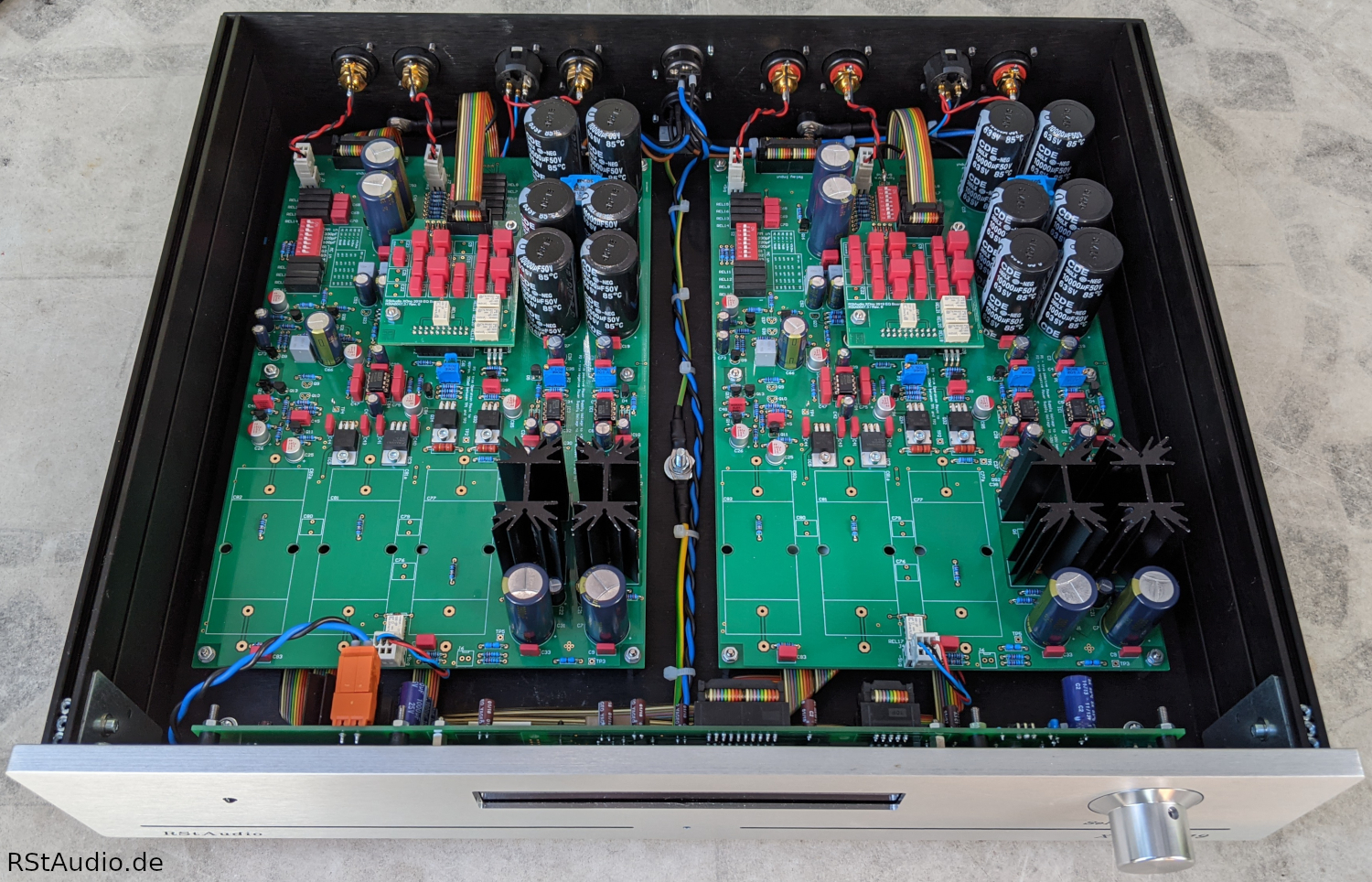
In the picture above you can see the opened RStAudio XOno 2019 audio case. It is completely equipped with relays, controller and EQ boards. As JFET’s the 2SK2145 are installed. In addition, this is the version with DC coupling, so with servo controllers.
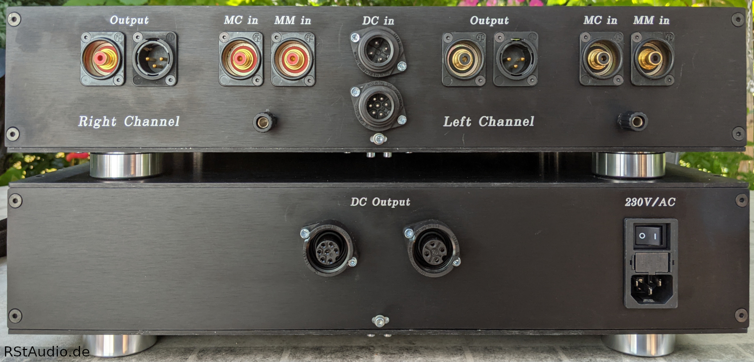
The front of the power supply unit is kept very simple. Since the RStAudio XOno 2019 is intended for continuous operation, the power switch is located on the back. Only one LED for the operating voltage indication is visible on the front panel.
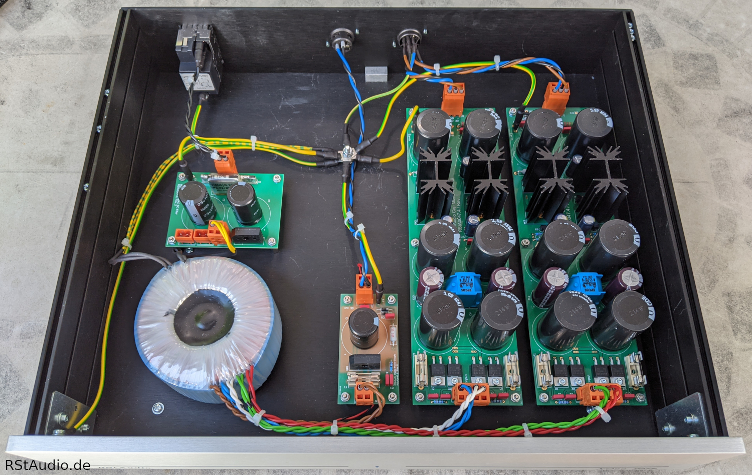
On the picture above you can see very nicely the electronic components for the power supply. On the back left you can see the power socket with switch, fuses and filter. Arranged in front is the DC filter and behind the frontside the toroidal transformer. I chose a single transformer with separate windings for the left and right channel.
On the right side are the boards for generating the unregulated operating voltages. On the far right are the two audio power supplies and more in the middle the simple power supply for the digital electronics.
Very nice to see is the central grounding point. All ground wires are wired directly to this point. You can also see very well how I have achieved a separation of the individual signal groups (230V/AC, secondary AC and DC) by the installation.
The following photo shows the front of the audio enclosure with the small EA W202 XLG display from Display Visions.
A very nice and detailed description of the assembly can be found on the pages of Meinolf Stute. He has documented the progress of his project with lots of fantastic photos. You get a very good impression of the project. By the way, his RStAudio XOno 2019 is fully equipped.
At the beginning of 2021, I built an RStAudio XOno 2019 for my friend Guido. The special thing about this unit is the front panels. Guido converted my logo into milling data and had them milled by a metalworking friend who, by the way, is the main supplier for Clearaudio. The result is a beautiful RStAudio XOno 2019. The fonts were deliberately not blackened, he just liked it better that way.

Audiophile Review
Ralph Stens (22-07-2020)
I’ve been listening to music with the prototype for quite some time now. First with the version with 2SK2145 and capacitor coupling, then with servo controllers. The XOno with the 2SK2145 is extremely low-noise, as I had already experienced with the test setup of the MC stage for my DPV1. Otherwise the version with capacitor coupling is a normal XOno, and I mean that in a very appreciative way! However this phono preamplifier wins again clearly when using the servo controls. For me this version is the best XOno I have ever heard.
So my recommendation is:
XOno with 2SK2145 and Servo Controls
With this solution you should be sure that the following input to which the RStAudio XOno 2019 is to be connected does not produce any DC voltage. If this is the case, you have to use capacitor coupling. However, such a DC voltage would be a serious mistake in the design of the following device.
More reviews about the RStAudio XOno 2019 can be found here.
FAQ
15-09-2020
For buyers of the circuit boards of the RStAudio XOno 2019 there is a protected FAQ page. The access code will be sent to you by me.
Printed Circuit Boards
26-08-2020
I provide the complete set of circuit boards of this project for self-builders. After an email request I will send a detailed list with all information.
If you would like to receive information about the PCBs you can use the following contact form.
Please make sure that you enter your e-mail address correctly. Otherwise, answers to your enquiry simply cannot be delivered. You can assume that I will reply to every request. If you don’t get an answer please check your SPAM folder.
Unfortunately, the contact form does not work for some users. In this case, please send me an e-mail to
info[at]rstaudio[dot]de
Please replace the information in the rectangular brackets accordingly (SPAM protection).